Your existing Mini-ITX case, a suitable ATX-compatible power supply, two M.2 2280 NVMe drives and some front-panel connections can form the basis of a Framework Desktop Mainboard build. A spare 120 mm fan may also be useful, but its dimensions alone do not qualify it. Framework specifies clearance, airflow, pressure and electrical conditions that need checking before you dismantle the old PC.
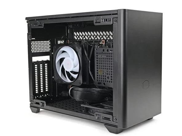
The major purchase is the complete Ryzen AI Max 300 Series mainboard configuration, including its fixed memory capacity. Your old RAM and CPU are not parts to move across. Start with a list of the equipment you want to retain, then resolve the cooling assembly, power connectors, SSD mounting parts, front USB adapter and wireless antenna arrangement around that board. The NR200 installation shown here is Framework’s example; it does not approve every case carrying an ITX label.
Choose the Board and Memory Capacity Together
The Ryzen AI Max 300 Series mainboard listing offers three configurations: Ryzen AI Max 385 with 32 GB, Ryzen AI Max+ 395 with 64 GB, and Ryzen AI Max+ 395 with 128 GB. Identify the exact configuration on the order, rather than treating “Framework Desktop Mainboard” as a complete specification. This article concerns those 300 Series boards.
Memory is the decision you cannot defer to a later DIMM purchase. Framework explains that the LPDDR5x memory is soldered and non-upgradeable. Existing desktop DIMMs or laptop SO-DIMMs therefore do not reduce the memory cost of this migration. If you need 128 GB, choose the board configured with that capacity; a plan to buy the 32 GB version and add modules later does not work.
The same inventory should distinguish the old processor and graphics card from the parts you are reusing. This is a new integrated platform, not a socketed replacement board for your existing CPU. Framework describes a PCIe x4 slot, not the conventional x16 graphics-slot arrangement that may be central to your current ITX system. Do not mark an old discrete GPU as retained on the strength of the case having expansion openings. This reuse plan is built around the new board’s integrated graphics.
That leaves plenty of useful equipment to assess: the enclosure and its fittings, PSU, storage, fans, front-port cables, displays and ordinary peripherals. Separating those from the platform components prevents an apparently inexpensive “board swap” from depending on RAM or expansion assumptions the board does not support.
Keep the Case Only After Checking the Cooling Space
Framework’s compatibility guidance requires a case supporting Mini-ITX or larger motherboards and at least 92 mm of internal height for the CPU fan and heatsink. The board outline is only the first fit condition. A slim enclosure that accepts Mini-ITX but provides less than that cooling height has not passed.
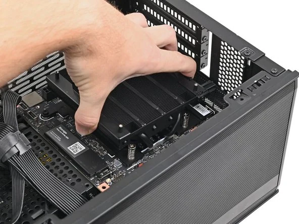
Check the actual space above the installed board position with the case assembled as you intend to use it. Side brackets, drive cages, cables and panel fittings belong in that check. Do not substitute the case’s external width for its internal cooling allowance, or assume removing a graphics card automatically leaves the required space in the right place.
In Framework’s guide, the mainboard is lowered into an NR200 with its original finned heatsink in place. Cables are moved out of the board opening first, and the rear ports must align with the case opening before fastening. This is useful evidence of how the board sits in a conventional enclosure, while the 92 mm requirement remains the screening condition for your own case.
Keep the case’s appropriate mounting hardware and check the board’s rear access as well. Framework warns that components on the underside may become inaccessible after installation. A case with an awkward back cutout may still take the board, but it changes when you must install the secondary SSD or wireless hardware. Plan that order before everything is screwed down.
Move Two Suitable Drives, Including the One Underneath
The platform provides two PCIe NVMe M.2 2280 slots. That makes a pair of existing 2280 NVMe drives useful candidates for reuse. Record each drive’s exact model and physical assembly, including any attached heatsink; “M.2” by itself does not establish NVMe compatibility or the right length.
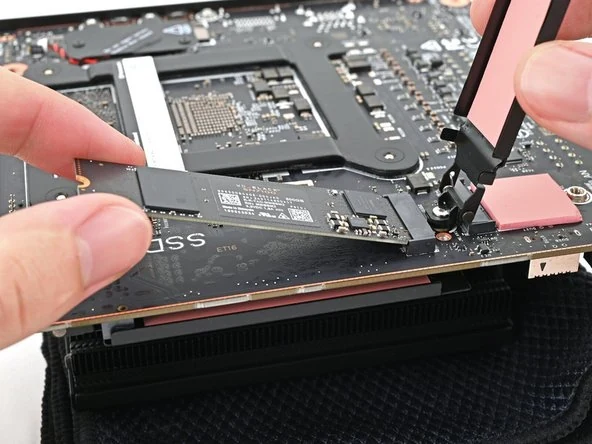
The secondary drive is on the underside of the mainboard. Framework’s installation sequence fits it before placing the board in the case. Its original heat spreader is secured with a captive T5 Torx screw; the guide shows opening the spreader, inserting the drive at an angle and fastening the assembly again. The photograph makes the access issue clear: this is work beneath the board, not simply a second top-facing socket you can always reach after assembly.
Keep track of the board’s storage heat spreaders, fasteners and supporting pieces. For a drive with its own pre-installed heat spreader, Framework provides a separate branch that removes the relevant board heat spreader. Do not stack two cooling assemblies just because both arrived with parts you own. Follow the appropriate branch for each drive and check the resulting thickness against the case.
The primary drive is installed from the other side in the later guide steps, also using its T5-secured heat spreader. Decide which existing drive will occupy each position before moving data or closing off access. Back up important files before dismantling the old machine, and retain the old system until the new hardware and operating-system plan are resolved.
An old SATA hard drive or M.2 SATA SSD is a different inventory item. The documented two-slot route here is NVMe; it does not establish a direct migration path for those SATA devices. Leave them outside the confirmed reuse list unless you have separately established a suitable connection plan. The same restraint applies to an unusually thick or high-capacity SSD: a matching length does not prove every physical variant fits.
Reuse a Fan That Meets the Cooling and Mounting Requirements
Framework recommends a 12 V, PWM-controlled 120 mm fan delivering at least 60 CFM and 2.0 mm H₂O pressure. Check your old fan’s actual specifications for all of those conditions. A quiet 120 mm case fan, a thin fan or a fan with a familiar brand name is not automatically an equivalent CPU-cooling choice.
The original heatsink stays with the mainboard cooling arrangement. An old AM5 tower cooler or an AIO from your previous motherboard is not the documented replacement for this assembly. Reusing a compatible fan is a narrower and more practical opportunity than assuming the complete old CPU cooler transfers.
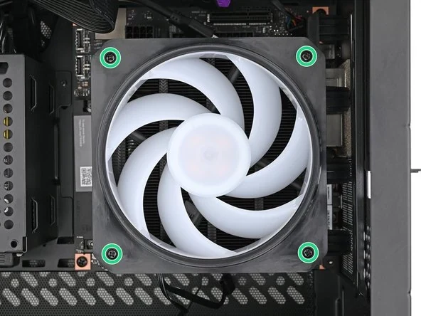
Framework’s guide lays the fan onto the heatsink, directs airflow toward the heatsink, then fits the fan duct with its lip upward. Four 27.3 mm-long Phillips screws secure the fan and duct. The green marks in the guide image identify the fastening positions. Check that your purchase includes the required mounting pieces, and that the selected fan works with that assembly; four holes alone do not establish the right stack height or screw engagement.
Use airflow direction as the controlling check when substituting a fan. The label-down orientation shown for the guide’s fan is helpful for that example, but Framework explicitly tells users of a different fan to orient it so it blows into the heatsink. Do not copy the appearance of the sticker while reversing the intended airflow.
Add up the Fan Current Before Connecting Extras
The compatibility page limits the three fan connectors to 2.4 A at 12 V in total. This is one shared allowance across the connectors, not 2.4 A available independently at each header. List the current rating of the CPU fan and any additional fans you intend to power from them.
For example, ratings of 0.8 A, 0.3 A and 0.3 A sum to 1.4 A. That arithmetic is an inventory example, not a measurement of your fans. Use the actual ratings and requirements of the chosen devices rather than copying the example numbers or treating the unused connectors as unlimited capacity.
The main fan connects to the four-pin header labelled “APU Fan”; Framework also shows an additional fan on “Sys Fan1.” If the chosen fan includes lighting, the guide treats that as a separate connection to a three-pin lighting header. A non-lighted fan skips that step. Do not assume an old lighting plug matches simply because the fan’s motor lead does.
This check also affects the power-supply recommendation below. A plan with extra fans is not the same as Framework’s basic one-fan configuration. Decide what you are actually retaining before choosing a wattage category or purchasing a lighting accessory.
Retain the Power Supply If Its Whole Installation Fits
Framework calls for an ATX-compatible power supply with 24-pin and 8-pin motherboard power connectors. It explicitly allows ATX, SFX, Flex ATX and other physical form factors. The electrical connection standard and the PSU’s physical size are separate questions: choose a supply that fits your retained case and provides the required connections.
You do not have to buy the Flex ATX supply developed for Framework’s own compact desktop merely because you are buying its mainboard. Conversely, an existing full-size ATX PSU does not fit every ITX enclosure. Keep the case’s mounting limitations, cable reach and space around the cooling assembly in the decision.
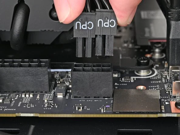
The close-up shows the CPU-labelled split 4+4 connector above the board’s 8-pin CPU socket. Framework’s guide separately connects the 24-pin main cable. Identify both required leads and retain the correct cables for your own PSU; a list saying “one eight-pin plug” is less useful than naming the CPU-power connection it must serve.
Framework gives two recommendations with different assumed loads:
| Planned configuration | Framework’s PSU recommendation |
|---|---|
| Basic use: 128 GB RAM, two SSDs, Wi-Fi, Ethernet, one 0.8 A APU fan, keyboard and mouse | 300 W |
| Using the PCIe slot, adding fans or expecting higher USB-port loads | At least 400 W |
These are recommendations for the stated arrangements, not a measured consumption figure for every possible build. Do not copy the 300 W value while silently adding expansion hardware and several extra loads. Equally, an owner whose suitable existing supply already meets the planned requirement has not established a need for a new PSU simply by choosing this board.
Keep Front USB Ports with the Correct Adapter
The board’s front-USB connection differs from the legacy header fitted to many older cases. Framework’s guide shows two USB Type-E 20-pin sockets above the primary storage. One accepts the appropriate front-port cable directly. For a case with the older USB 3.0 front-header connector, the next step uses an adapter to reach the other Type-E socket.
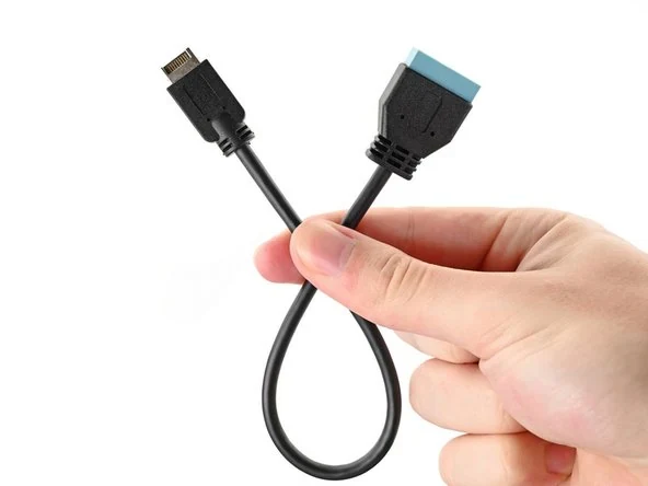
The adapter photograph is particularly useful: its narrow Type-E end and larger legacy front-USB end are visibly different. The guide calls the legacy connection “USB 3.0 20-pin”; it is also commonly described by its 19 populated pins. Identify the connector itself rather than assuming two products called “20-pin USB” mate directly.
For an older case with front USB-A ports, inspect the cable coming from those ports and establish the required Type-E-to-legacy-header adapter. For a case with a suitable front USB-C cable, identify its Type-E connection separately. An adapter for one branch is not a reason to assume every front port is already connected.
Keep connector shape, cable reach and port capability as separate checks. An adapter can provide the documented connection route, but this does not establish that an old case’s front ports acquire every capability associated with the new board. The goal is to retain usable existing ports without buying the wrong internal adapter or overstating their resulting speed.
Preserve the Power Switch and Front Audio as Separate Connections
Framework’s installation guide connects the case’s front-panel cable to a nine-pin connector beneath the primary storage. It connects the HD audio cable to another nine-pin connector beside the main power connector. These are separate destinations; pin count alone is not an identification method.
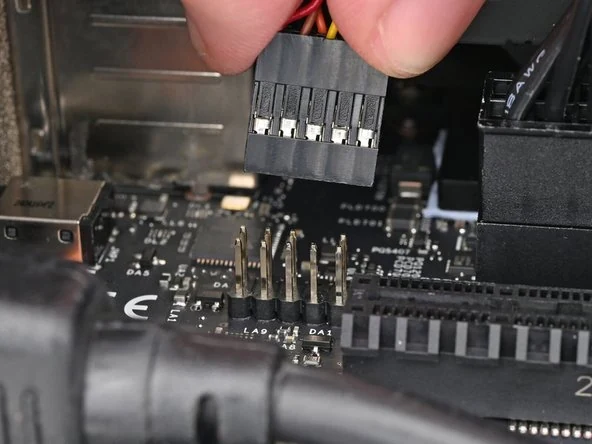
The audio photograph shows the keyed plug aligned over its header. Keep the case’s HD audio cable if it matches the documented arrangement and reaches the connection point. Do not substitute a USB cable or a front-switch plug because it happens to occupy a similar-sized block of space.
For the switch and indicator wiring, identify the case’s connector arrangement and use the board’s documented front-panel information. If the old case has individual connectors rather than the block shown in the example, resolve the mapping before installation. Do not copy a guessed pin layout from a different motherboard. The reusable item is the case’s functioning switch assembly and wiring, subject to the correct connection—not an assumed universal plug orientation.
Finish the Wireless and Rear-port Inventory
Framework’s platform description identifies Wi-Fi 7 through an RZ717 module. Its installation guide shows why the module is only part of the wireless inventory: there are two antenna cable connections, a shaped retaining bracket and a securing screw. The case’s antenna arrangement must also be present and appropriate.
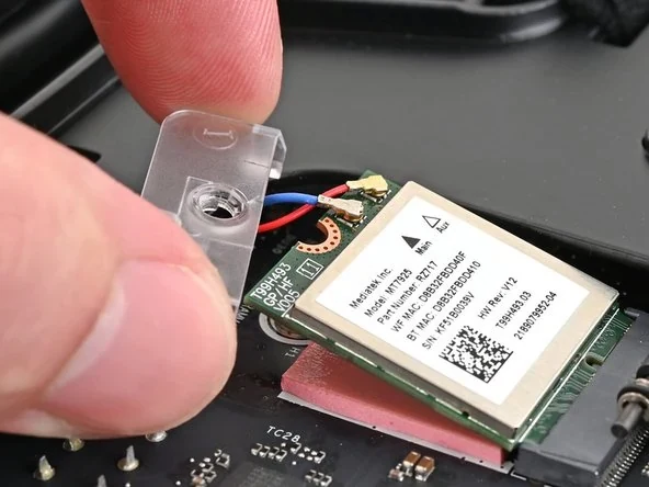
The guide explicitly assumes that a PSU and antenna module are already installed in the example case. Do not turn that starting assumption into a promise that every bare-mainboard order contains the case’s external antenna hardware. Check the actual contents of your chosen package and the equipment already installed in your case.
The wireless bracket photograph shows the small parts that can disappear from a casual used-parts list. Preserve the bracket and correct fastener, identify the antenna leads and confirm the matching connections. Framework warns that the miniature connectors are delicate and says the cable colours depend on the antenna module; follow that module’s instructions rather than copying wire colours from a photograph.
Rear connectivity offers other reuse opportunities. Framework lists two USB4 ports, two DisplayPort outputs, HDMI and 5 Gbit Ethernet. Match your existing displays, cables and peripherals to their required connections. That list does not guarantee that every display will operate at its maximum resolution and refresh rate simultaneously, or that an existing network will deliver 5 Gbit throughput.
If your intended desktop uses Ethernet, record that decision rather than adding an unrelated wireless shopping item by default. If you need Wi-Fi, resolve the complete module, retention and antenna chain before the back of the board becomes difficult to access.
Turn the Reuse Decisions Into One Complete Purchase List
Consider an owner whose existing case provides the required cooling height and suitable board access, whose PSU meets the chosen load category, and whose two 2280 NVMe drives fit the documented storage assemblies. If the spare fan meets Framework’s recommendation and works with the duct hardware, those components may all stay. The remaining purchases can be the chosen CPU-and-memory mainboard configuration, any missing mounting pieces and the front-USB or antenna items actually absent.
Now change the case to a very slim model with less than 92 mm available for the heatsink and fan. Even with suitable storage and a powerful PSU, the enclosure has failed the first cooling screen. Choosing a thin fan on appearance alone does not establish an approved substitute cooling assembly. Resolve the case and cooling arrangement before ordering the board around that enclosure.
A third owner may have sufficient case clearance but an old fan without the required airflow and pressure specifications, legacy USB-A wiring and incomplete antenna hardware. That is a different basket: retain the case and suitable PSU and drives, but resolve the CPU fan, Type-E adapter and complete wireless arrangement. Do not call the upgrade “mainboard only” while leaving those necessities to chance.
Before retiring the old PC, your list should identify the exact 300 Series board and fixed memory capacity, case clearance, PSU and its original leads, both drive positions and thermal parts, qualified fan and duct fasteners, total fan current, front-port connections and intended network arrangement. Back up the data and decide how the operating system will be installed or transferred. When each branch has a real answer, the old enclosure and useful accessories become a coherent new desktop rather than a collection of parts that merely share familiar standards.