The DA2 V2 can preserve a standard ATX power supply, but that choice consumes drive-bracket space and limits the graphics card to 220mm in the normal layout. Moving to a compact SFX or SFX-L supply can release space; accommodating a substantially thicker card may also require the dedicated DA2 Vertical GPU Kit, a different CPU cooler and a mini-ITX motherboard. The adjustable rails help arrange those parts, but they do not make all the case's published maximums available together.
Start with the parts you most want to keep. If the old PSU, short graphics card and current cooler are valuable, a conventional layout may be the sensible route. If the intended graphics card is the priority, price the whole cooling, mounting and power arrangement around it. Buying a riser or changing the PSU alone does not establish that the finished system fits.
Start with the Normal Layout
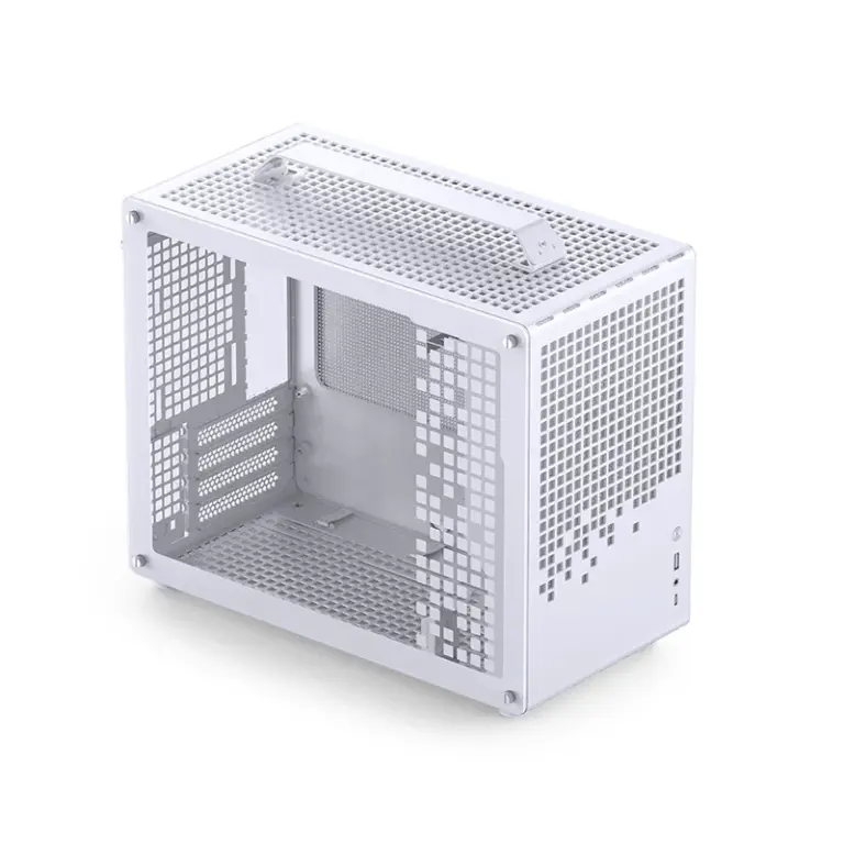
The open-case view shows the DA2's tracks and brackets around a largely unobstructed interior. Horizontal and vertical universal brackets mount along the frame, while separate dedicated brackets support the PSU and drives. This is a configurable mounting system rather than a set of isolated fixed bays. Moving one bracket changes where the hardware beside it can sit.
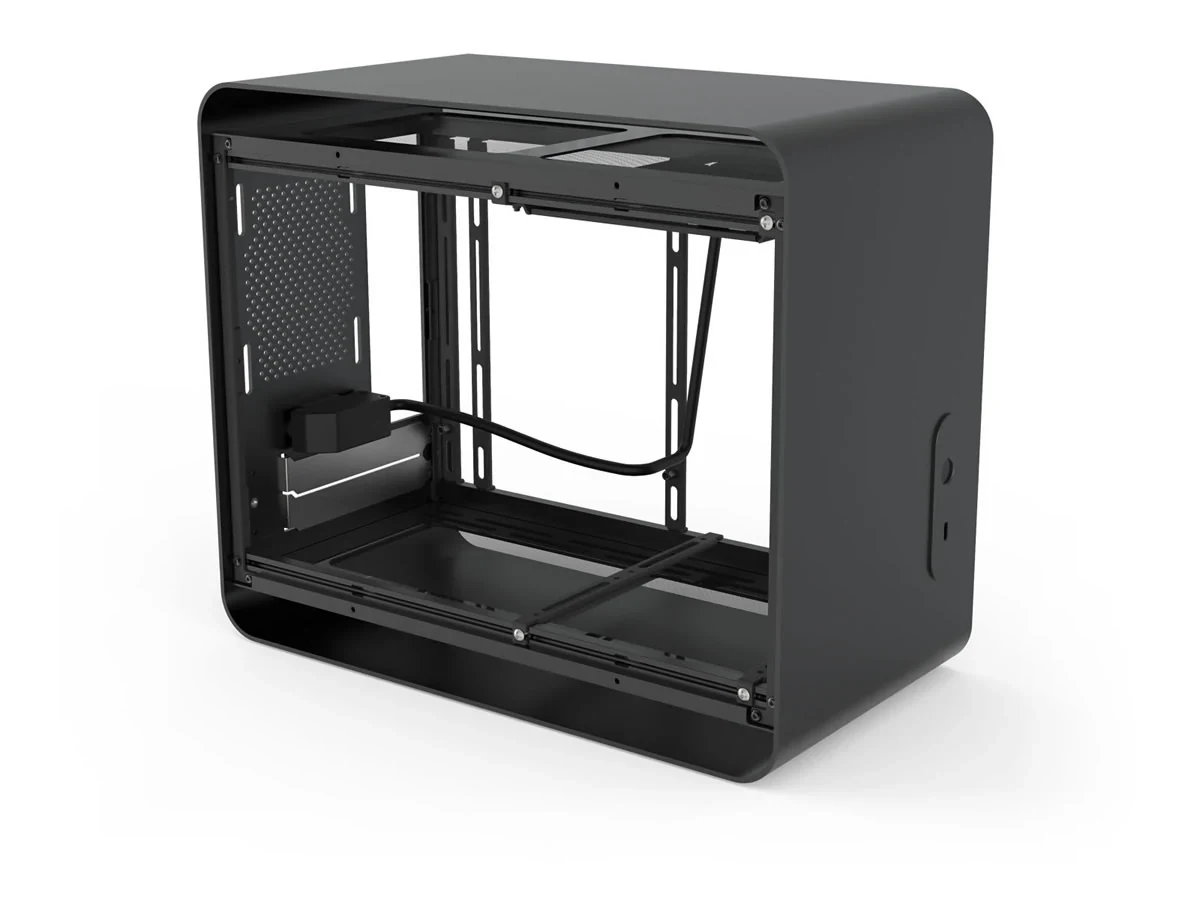
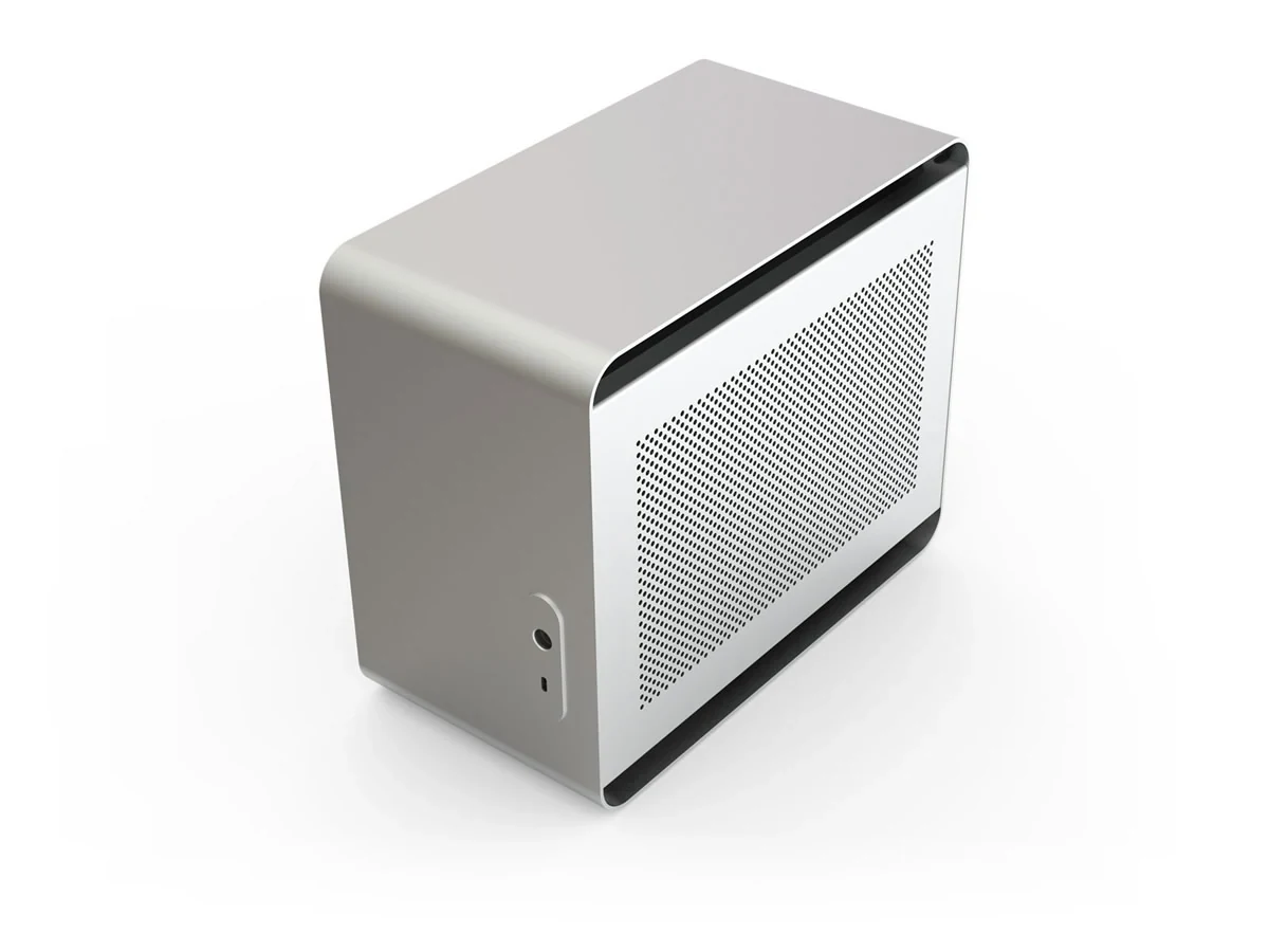
In the normal arrangement, the case supports mini-ITX or mini-DTX motherboards, a directly inserted dual-slot graphics card and a tower cooler up to 145mm tall. Its external dimensions are 340mm deep, 286mm high and 180mm wide, with a stated 17.5-liter volume. Leave space for the actual rear connections and keep the intended intake and exhaust surfaces clear at the desk.
For the graphics card, use the current recommendation of 323 × 150 × 50mm as the starting envelope. The product page also displays a 330mm headline, and the manual lists 330mm. Those larger figures are not a reason to buy a 323–330mm card without checking its exact shape and connections with Streacom. The body, protruding shroud and power-cable bends all belong in the fit decision.
Thickness needs the same care. Streacom explains that the physical distance from the PCIe slot to the lower acrylic panel is 56mm, while its 50mm recommendation reserves room for tolerances and airflow. Do not convert the 56mm gap into approval for a 56mm card. Removing the acrylic panels is described as possible, but it also changes filtration; it is not the default route for retaining the normal filtered enclosure.
What Keeping the ATX Supply Uses up
The mounting illustration shows the dedicated PSU bracket and the alternative arrangements for SFX-L and ATX supplies. An ATX supply uses the PSU and drive brackets together, with three screws through the ATX mounting slots. The unused fourth PSU mounting hole is part of the documented arrangement, not evidence that a random extra fixing needs to be improvised.
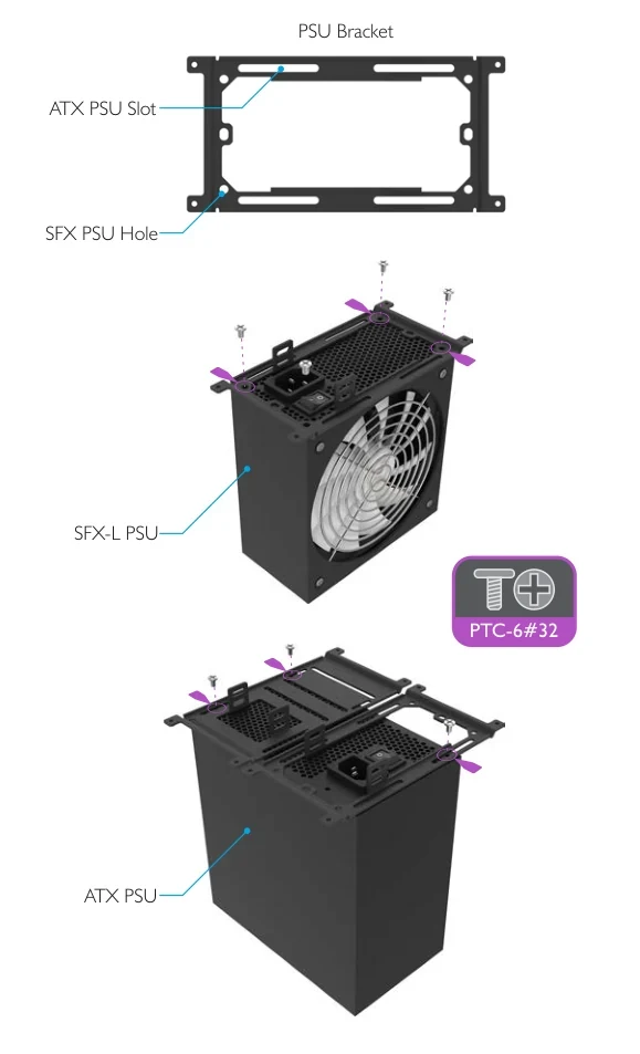
That combined assembly occupies space otherwise available to drives and the graphics card. Streacom specifies a 220mm maximum expansion-card length with an ATX supply. If the retained card is longer, the normal ATX-PSU arrangement fails that first screening step even though the case is advertised with a much longer general GPU figure. A larger PSU and a long card cannot each claim the same space.
Also identify the actual PSU's length and cable exits. “ATX” describes a family of supplies, not a promise that every housing and bundle fits this arrangement. Check the whole supply with its original matching cables and the remaining drive plan. Do not treat an unspecified old ATX unit as confirmed merely because the mounting screw pattern is familiar.
The original IEC extension must reach the PSU inlet. The manual calls for connecting its C13 plug and setting the PSU switch before the bracket assembly blocks access; do that preparation with the system disconnected from mains power. If a large motherboard I/O assembly obstructs the rear C14 socket's cable exit, the manual allows the socket to be rotated. Keep the original finished lead and mounting hardware rather than modifying the mains wiring.
Two small supplied parts can matter. A 2mm spacer clears a PSU switch that would otherwise hit the bracket lip. Separate standoffs lower the PSU by 14mm to make room for the power plug when arranging a slim fan above it. Neither creates free space everywhere: lowering the supply changes what can occupy the area beneath it.
Treat the Drive Bracket as Shared Space
The drive-bracket detail shows why the PSU decision comes first. It has slots for the drive arrangements, but also ATX PSU mounting slots. If the bracket is helping to hold the old ATX supply, its nominal storage capacity is not automatically available at the same time.
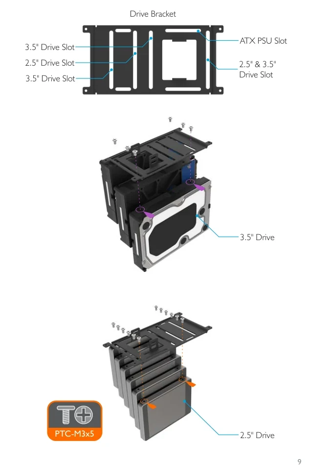
The manual describes three 3.5-inch drives or six 2.5-inch drives per bracket, with each 3.5-inch drive occupying the equivalent space of two 2.5-inch drives in a mixed arrangement. The current product page describes typical configurations of three 3.5-inch or five 2.5-inch drives. Treat the bracket's six-drive mounting pattern as a component-level description, not a guarantee that six populated devices fit every finished build.
For example, one 3.5-inch disk and two 2.5-inch SSDs account for four of the bracket's six nominal 2.5-inch positions. That arithmetic helps describe the bracket, but does not settle whether the remaining positions are usable beside the selected PSU, radiator or cables. Assign each retained drive a location and check the connectors at that location.
SATA data plugs, power plugs and the wiring between them extend beyond the drive body. Include them when checking the space behind a side radiator and around the PSU. The rails may permit another mounting position, but a position already occupied by cooling hardware is not an additional drive bay to count again.
For a drive-heavy reuse plan, keeping a compact supply may be more valuable than preserving the old ATX unit. For a short-card system with little SATA storage, retaining the ATX unit may avoid an unnecessary purchase. Decide from the actual drive inventory rather than the largest number printed beside “drive support.”
Check the Whole Side Radiator Assembly
The manufacturer's bracket illustration shows a side radiator occupying the same general interior that must also accommodate the supply, motherboard connections and cable paths. It makes the rail system's flexibility visible, but the pictured arrangement does not verify the dimensions of a different AIO or graphics card.
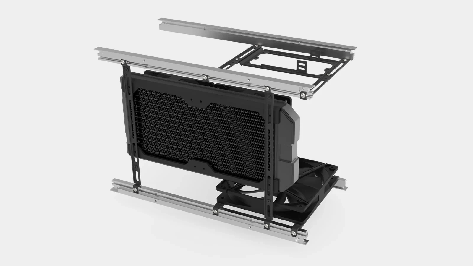
The current specification supports radiators from 120 to 280mm and gives 80mm total thickness including fans. The manual's SFX-based example shows an 82mm gap and explicitly says to consider radiator thickness, fans and tubing, with additional allowance for tolerances. Use the current 80mm figure for initial planning, then verify the whole assembly and its hose route within the actual available space. Do not spend the last 2mm on the assumption that the older drawing provides a usable margin.
The radiator's advertised fan size is only one measurement. End tanks, fittings, the fan frames and the bend where tubing leaves the radiator can decide whether it clears the PSU or motherboard area. Similarly, a pump block and its connections must fit the chosen motherboard and layout; a nominal radiator match does not establish all those relationships.
Plan the side assembly before purchasing it, but leave its final installation until the other connections are accessible. The manual recommends fitting the AIO after the other hardware because the radiator and tubing obstruct access. Connect and secure the cables before mounting the side bracket, and check that none can contact a fan.
If retaining an existing AIO is essential, record its complete dimensions and tubing exits first. A confirmed compact PSU plus a suitable 240mm assembly may be a coherent plan; “the case supports 280mm” is not confirmation that a particular thick 280mm package will fit around your retained parts.
Plan Fans and Filters Around the Hardware
The current specifications allow up to 200mm fans on the vertical universal brackets, 120mm on the horizontal brackets and 92mm at the rear. The case does not include fans, so a bare enclosure purchase leaves that choice to you. Check which mounting position remains available after the PSU, drives and radiator have been assigned.
There is another mounting route on the upper and lower acrylic panels. Their silicone mounts accommodate 120mm or 140mm fans without using the horizontal brackets. Streacom recommends ultra-slim 13–14mm fans when nearby hardware leaves little room. That does not change the horizontal-bracket limit to 140mm; it is a different attachment method with its own clearance requirements.
The upper and lower assemblies include acrylic panels with a PVC filter net between them. Keep those pieces in the case inventory, along with the silicone mounts if you intend to use panel-mounted fans. The manual recommends installing those fans early, when other hardware will not obstruct access.
Only one magnetic side dust net is supplied. Decide which side actually draws air inward rather than assuming that both side panels have nets in the box. A second net is an additional part, and a filter on an exhaust side is not automatically useful. The final arrangement still needs unobstructed airflow; these mounting options are not temperature or noise results for your finished build.
What the Vertical Kit Actually Changes
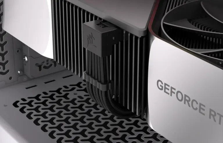
The dedicated kit view shows a replacement rear panel, a flexible riser and a horizontal support bracket. This is a DA2-specific conversion, not a generic riser added to the normal rear slots. It supports DA2 V1 and V2 enclosures, but excludes DTX motherboards. A retained mini-DTX board that fits the ordinary case therefore does not remain eligible for this route.
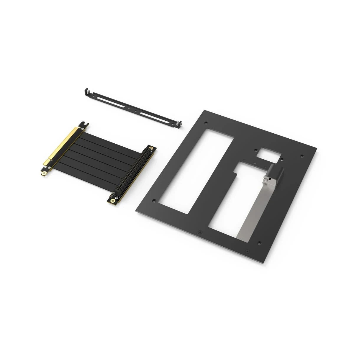
The kit includes a 100mm PCIe ×16 flexible riser and a single-slot PCI mount. Keep the case's original dual-slot PCI mount: the installation guide explicitly reuses it with the new rear panel to secure the card. When assessing a used case and loose conversion kit, verify both mounts rather than assuming the new box replaces every original fixing.
The motherboard position also changes. The guide relocates it toward the bottom by reorienting its mounting brackets and swapping brackets 1 and 2. The standoffs stay attached to the brackets. Mark the original positions and follow the kit's spacing illustrations; this is not achieved simply by rotating the graphics card while leaving every other component where it was.
Transfer the original rear IEC socket with the proper hardware, and account for the horizontal bracket if the card needs support against sag. Do not regard the riser as the card's mechanical support. The optional glass side-panel kit is separate; it is not required merely because the vertical-card examples show a display-oriented build.
The supplied riser is certified for PCIe Gen3. Streacom says Gen4 compatibility depends on the hardware and that some board/card combinations require Gen3 operation. Do not buy it as an unconditional Gen4 or Gen5 riser, or assume a newer card will operate correctly just because the connector is ×16. Resolve the exact board, card and riser combination before making the conversion dependent on it.
Pair Card Thickness with CPU Cooler Height
The installed rear view shows the changed expansion-slot direction. The useful benefit is space for a thicker card, but the card and CPU cooler still divide a finite interior. Streacom's dimension drawing pairs the three mounting positions as follows:
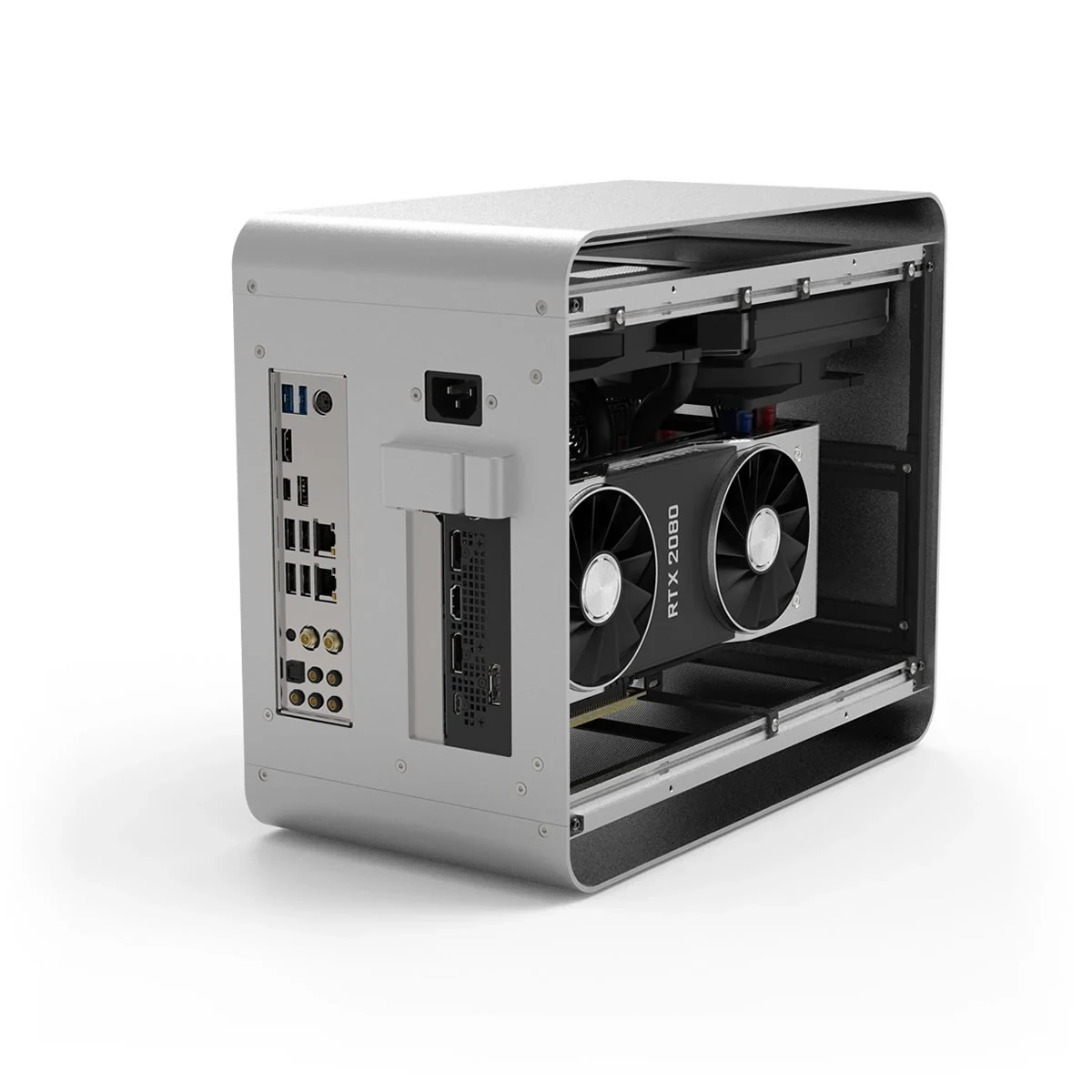
| Vertical mounting position | CPU cooler height limit | Card thickness shown in the drawing |
|---|---|---|
| Slot 3 | 104mm | 44mm |
| Slot 2 | 84mm | 64mm |
| Slot 1 | 64mm | 84mm |
Choose a row as a relationship. The 104mm CPU clearance and 84mm card thickness belong to different positions; they are not a combined maximum configuration. A 145mm tower cooler retained from the normal layout also exceeds all three vertical-layout CPU limits. A thicker-card purchase can therefore require replacing a perfectly serviceable cooler.
For example, if your intended card needs the 64mm thickness envelope, start with the corresponding 84mm CPU clearance, then check the actual cooler and surrounding components. Do not round a card's marketed slot count into one of these dimensions. Measure its real shroud and include protrusions and the power connection in the case-specific check.
Streacom's other drawing shows an 88mm space above the illustrated relocated motherboard. That is useful for understanding why the conversion consolidates room at the top; it is not approval for any radiator, fittings or fan package totaling 88mm. The PSU, drive locations and cable paths still have to be arranged around the chosen card and cooling assembly.
Likewise, do not transfer the ordinary layout's 323mm recommendation or ATX-PSU 220mm limit into a blanket vertical-layout approval. The card has changed orientation and the motherboard has moved. Confirm the complete vertical arrangement, including card length, connectors, PSU and storage, with the actual parts before treating it as a finished purchase list.
Check the Front Port and Original Small Parts
The original front-I/O illustration shows the Type-C socket connected to a standard 19-pin USB 3.0 motherboard header. The supplied cable provides the 5Gb/s route; the Type-C shape does not make it a native internal Type-E or 10Gb/s connection. Check the header on the retained motherboard, especially if the previous case used a different internal cable.
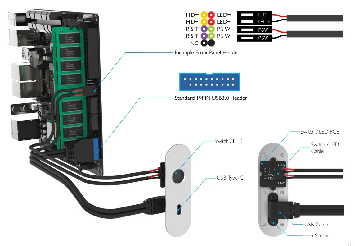
The front module can be changed, and Streacom lists optional faster-cable and Type-A arrangements. Those are separate items to verify, not equipment to count as included with the basic V2 case. If the original cable is already suitable, keep it rather than buying an upgrade solely to match the port's shape.
The stock front panel provides the power switch and indicator, but no reset switch, drive-activity indicator or front audio connection. Check whether losing those features matters for how you use the existing desktop. Follow the motherboard's own header diagram when connecting the switch and LED; the manual's pictured motherboard is illustrative.
For a used enclosure, also retain the bracket screws and captive nuts, rubber panel catches, acrylic filter assemblies, IEC extension, PSU spacers and original PCI mount. The rail system is useful only when the hardware that secures the parts is still present. A missing small bracket can change the cost of a seemingly inexpensive case move.
Compare the Complete Retention Plans
A conventional reuse example might keep a mini-ITX board, a suitable tower cooler under the 145mm limit, a short dual-slot graphics card and the old ATX PSU. That is worth investigating when the card satisfies the 220mm ATX-layout limit and the retained drives have confirmed positions. The saving is the PSU and cooler you can keep; the sacrifice is the space taken by their arrangement. Neither a long card nor the maximum drive count should be silently added to that plan.
A thicker-card example might keep the mini-ITX platform while changing to a compact supply, the dedicated vertical kit and a CPU cooler appropriate to the chosen clearance row. The decision is then whether the card justifies replacing those other parts. A mini-DTX board, unidentified riser behavior or unconfirmed card envelope prevents that particular plan from being considered complete.
| Inventory question | Conventional ATX-retention route | Vertical-card route |
|---|---|---|
| Motherboard | Mini-ITX or mini-DTX, exact fit checked | Mini-ITX; DTX excluded |
| Power supply | Exact old ATX unit, original leads, combined bracket mounting | Exact compact supply and cable route checked with the new layout |
| CPU cooling | Suitable normal-layout cooler, up to 145mm tower height | Cooler matched to the selected 104/84/64mm position |
| Graphics hardware | Suitable direct-slot card, up to 220mm with ATX PSU | Exact card envelope, dedicated rear panel and riser, both required PCI mounts |
| Drives | Individual positions after PSU space is allocated | Individual positions after card, PSU and cooling are allocated |
Before dismantling a working PC, settle the unresolved item that changes the route: the PSU-and-card combination, the retained disk positions, the AIO's complete envelope or the vertical kit's board compatibility. Once those relationships are clear, the sliding brackets help assemble the plan. They should not be used as a reason to buy incompatible parts and hope that another bracket position will solve the conflict.