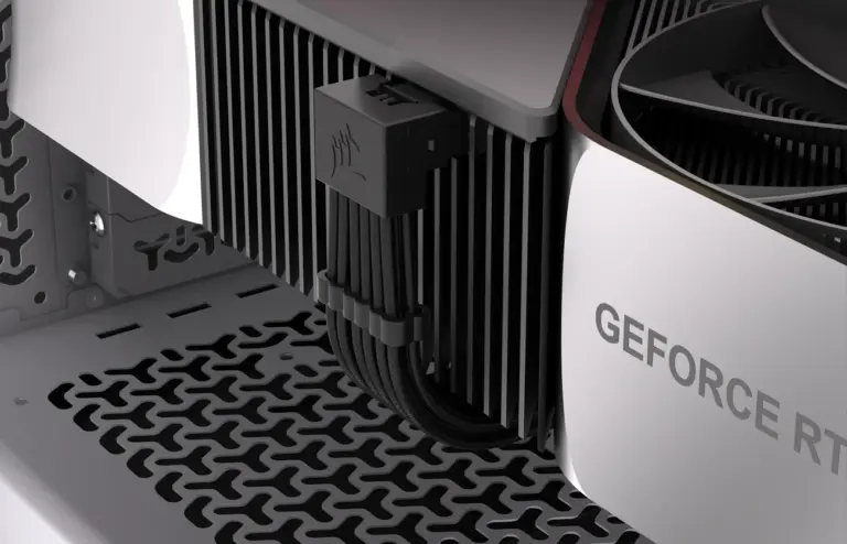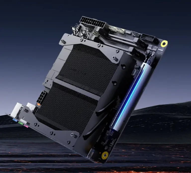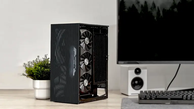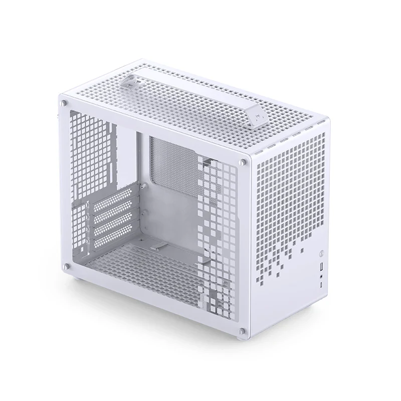
You can keep an existing ATX power supply and 240 mm AIO in the Jonsplus Z20 when the complete PSU, cooling and graphics-card combination matches its installation table. The useful question is which table entry fits your parts—not whether the case separately advertises ATX power, a 240 mm radiator and a 363 mm graphics card. PSU body length and the motherboard's graphics-card position change the answer.
The tables below cover the six ATX PSU lengths, three top-cooling arrangements and two graphics-card positions in the original Z20 guide. Then check the SFX alternatives, bottom fans, retained drives and support hardware. A passing length entry is a starting point for a complete migration plan, with cable connections and installation access still to resolve.
Start with the Motherboard and the Parts You Want to Retain
This guide uses the white tempered-glass Z20 V1.0 product specifications and its original user guide. The case supports Mini-ITX and full-size Micro-ATX motherboards and has four expansion slots. Identify where the motherboard's graphics connector places the installed card relative to the case's first or second expansion-slot row. That physical position selects the corresponding GPU-length row in the compatibility table.
Do not choose the more generous row merely because the motherboard has another connector somewhere lower down. The table describes the card's installed case position, which depends on the board. Record the actual retained motherboard and card arrangement before comparing it with the PSU options.
Measure the PSU's body length separately from its connected modular plugs and cable bends. For the GPU, use the same length definition as the guide: its table excludes the bent part of the PCIe metal mounting bracket, approximately 12.5 mm. A retailer's overall measurement or your own ruler measurement may use a different endpoint. Establish that correspondence rather than blindly subtracting 12.5 mm from every published card specification.
Also list the cooler type, radiator-only thickness, fan thickness, card thickness, 2.5-inch drives, any 3.5-inch drive and the GPU support you want to retain. Each item occupies part of a shared space. The case photograph identifies the actual enclosure; the component list determines which internal arrangement is relevant.
Use the Six-Length ATX Matrix with the Correct Top-Cooling Branch
The front PSU mounting system has four positions, P1 through P4. For the combinations in the original table, the recommended position is P1 with two top 120 mm fans, and P2 with either two top 140 mm fans or a top 240 mm radiator. The latter two branches share the same listed GPU lengths, but their thickness conditions describe different objects.
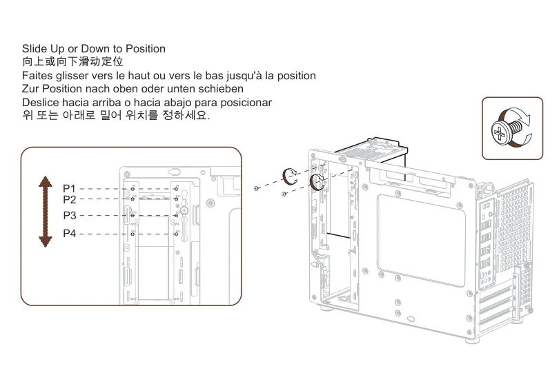
The three top configurations are:
- Two 120 mm fans: fan thickness no more than 38 mm, PSU position P1.
- Two 140 mm fans: fan thickness no more than 30 mm, PSU position P2.
- A 240 mm water-cooling radiator: radiator-only thickness no more than 30 mm, PSU position P2.
The product specification additionally describes a 240 mm radiator-and-fan assembly up to 60 mm thick. Do not apply that 60 mm figure to the bare radiator.
All GPU values in this table are millimeters under the guide's bracket-excluding length definition. “Slot 1” and “Slot 2” mean the case positions described above.
| ATX PSU body length | Two 120 mm fans, P1: Slot 1 GPU | Two 120 mm fans, P1: Slot 2 GPU | Two 140 mm fans or 240 mm radiator, P2: Slot 1 GPU | Two 140 mm fans or 240 mm radiator, P2: Slot 2 GPU |
|---|---|---|---|---|
| Up to 130 mm | 363 | 363 | 363 | 363 |
| 140 mm | 363 | 363 | 363† | 363 |
| 150 mm | 363† | 363 | 280‡ | 363 |
| 160 mm | 280‡ | 363† | 280‡ | 363† |
| 170 mm | 280‡ | 363† | 273 | 280‡ |
| 180 mm | 273 | 280‡ | 273 | 280‡ |
If your PSU sits between the table's listed lengths, do not interpolate a custom GPU allowance. Check the exact body, connector area and intended mounting position against the guide or manufacturer before treating that unlisted combination as confirmed.
The symbols retain the original table's answer-changing footnotes:
† Cable-planning note: for a longer graphics card in these entries, the guide says custom-length modular PSU cables make installation and cable management easier. This is advice, not a statement that custom cables are included or that every card requires a special cable set. Any replacement modular lead still needs to match the exact PSU.
‡ Output-port note: the guide says the maximum GPU length may increase by about 20 mm depending on the actual PSU output-port position and installation direction. Treat that as a detail to verify on the particular PSU and layout, rather than automatically adding 20 mm to the table. The unmarked 273 mm entries do not receive a general extra allowance from this footnote.
For example, an owner keeping a 150 mm ATX supply, a 240 mm AIO and a 310 mm GPU gets a different initial result in the two case positions: the Slot 1 row lists 280 mm, while Slot 2 lists 363 mm. That example does not establish that moving the card to another motherboard connector is appropriate. It tells you to check the retained board's real layout before deciding whether the PSU can stay.
Similarly, a 140 mm supply and a long card can remain a candidate in the 240 mm branch, subject to the marked cable-planning condition and the rest of the assembly. The P1–P4 rail diagram helps identify the mounting positions. The presence of P4 is not permission to override the specific P1 or P2 combination with a guessed lower position.
Compare SFX Side Mounting with SFX Vertical Mounting
An existing compatible SFX or SFX-L supply gives you another route. Jonsplus describes side mounting as avoiding the front PSU interference with the cooler and GPU, while vertical mounting uses the included SFX-to-ATX conversion plate. The table lists the following SFX configurations.
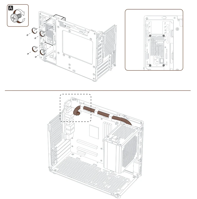
| Top cooling | Side-mounted SFX route | Vertically mounted SFX route | Listed GPU length in either case position |
|---|---|---|---|
| Two 120 mm fans, up to 38 mm thick | Side position | P1, P2 or P3 | 363 mm |
| Two 140 mm fans, up to 30 mm thick | Side position | P2 or P3 | 363 mm |
| 240 mm radiator, up to 30 mm radiator-only thickness | Side position | P2 or P3 | 363 mm |
These entries preserve the same GPU-length measurement boundary. They do not remove the need to check card thickness, connected plugs, radiator fittings or drive placement. In particular, the side-mounted PSU can conflict with the side SSD arrangement; the SSD section of the guide explicitly identifies that possibility.
The native side-mounting illustration also shows the CPU power-cable route. The guide advises connecting that cable first after installing the supply. Include access to that connection in the assembly plan rather than assuming a retained cable can be reached easily once every large component is installed.
A suitable ATX supply that already passes the relevant branch remains a sensible part to keep. SFX is an alternative layout, not an automatic instruction to buy another PSU. If a replacement becomes necessary, resolve the complete system's electrical requirements and the exact cable set alongside its smaller physical format.
Check the Cooler Assembly and the Space Under the Graphics Card
The Z20 supports a top 240 mm cooling assembly within the stated limits. Measure the radiator and fans as a complete stack as well as separately, and check the actual fittings and tube route. The 30 mm bare-radiator limit and 60 mm radiator-plus-fan description apply together; a product called “240” does not establish either measurement.
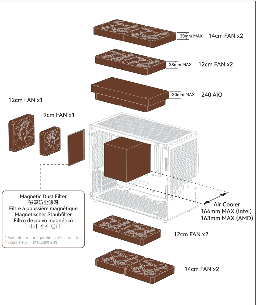
For an air-cooled alternative, Jonsplus lists a maximum tower height of 164 mm with an Intel CPU and 163 mm with an AMD CPU. Preserve that distinction when checking an existing tower. Cooler height is a mechanical clearance, not a prediction that any retained CPU will have a particular temperature in the case.
The original cooling-position illustration shows top, rear and bottom choices. The product page describes a rear 120 mm fan for an air-cooled setup; where an AIO's rear tube route conflicts, it identifies a 92 mm rear fan or leaving that location empty as alternatives. Plan the route actually used by the retained AIO rather than adding every fan from the maximum fan list.
Jonsplus gives 89 mm from the graphics-card backplate to the case bottom. That is a shared budget for the card's thickness in the relevant direction, any bottom fan and the remaining clearance. Make sure the dimensions you subtract use the same reference plane. A slot-count label alone is too coarse for this check.
For example, a hypothetical 70 mm card allowance plus a 15 mm fan totals 85 mm. Being numerically below 89 mm is not a complete fit verdict: actual reference points, protrusions and breathing room still matter. The product page itself suggests slim 12015 fans or no bottom fans for some graphics cards. Treat bottom cooling as conditional on the installed GPU and storage arrangement.
For a long card, also check how it enters the case. Jonsplus describes a removable PCIe-slot fixing strip for installation of cards longer than 345 mm. That installation access feature does not increase the GPU length permitted by your PSU-and-cooling table entry.
Keep the Thin SSD Mounting Limits Attached to the Actual Positions
The specified maximum of three 2.5-inch SSDs is described as two side-mounted drives plus one bottom-mounted drive. It is not a promise that three arbitrary drive assemblies fit alongside every PSU, HDD and bottom-fan option. Use the actual drive thicknesses and mounting positions in the guide.
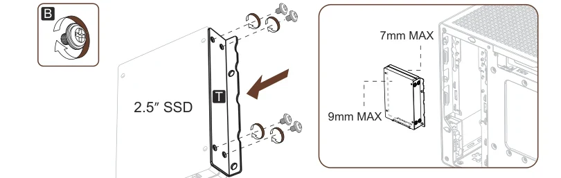
The side SSD illustration labels one mounting plane for up to 7 mm and the other for up to 9 mm. Do not turn that into two 9 mm positions. Retain the dual SSD mounting bracket and the appropriate screws, and account for the guide's instruction to remove the upper cable-management Velcro when using this arrangement.
The same section warns that an SSD may conflict with the side-mounted SFX supply and suggests the case bottom as another location. Moving one drive there consumes a bottom position; it does not create an additional side slot or prove that the original three-drive maximum survives the change. Recount the drives after selecting the PSU mounting route.
The bottom SSD arrangement is compatible with two 120 mm fans or one 140 mm fan. Jonsplus's later storage description also retains the GPU support bracket in that arrangement. Check these as a named combination rather than adding the SSD maximum, HDD maximum and fan maximum from separate specification lines.
Choose the HDD Arrangement Together with the GPU Support
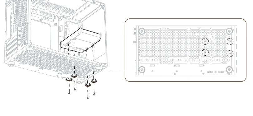
For one retained 3.5-inch HDD, the guide provides standard and additional mounting arrangements. “Additional” describes the alternative bracket position, not an independently verified second HDD bay. Jonsplus lists the case's 3.5-inch capacity as up to one drive.
| Bottom storage arrangement | Fan combination described for that arrangement | GPU support bracket |
|---|---|---|
| One bottom-mounted 2.5-inch SSD | Two 120 mm fans or one 140 mm fan | Retained in the product's described combination |
| One 3.5-inch HDD, standard mounting | One 120 mm or one 140 mm fan | Compatible |
| One 3.5-inch HDD, additional bracket mounting | Two 120 mm fans or one 140 mm fan | Incompatible |
The additional-HDD diagram shows how its bracket occupies a different part of the lower compartment. If your plan needs both a 3.5-inch drive and two bottom 120 mm fans, it is the route to examine—but it gives up the case's GPU support bracket. If the existing GPU needs that support in your planned build, choose a different combination rather than counting all three items as simultaneously retained.
The support hardware itself has a lower-position option for a thicker graphics card. The guide illustrates changing the support pad's position from 23.5 mm to 8.5 mm. That is an adjustment of the support assembly, not an extra 15 mm of fan clearance or a way to override the HDD bracket conflict. Retain its matching parts if the selected layout uses the support.
These storage decisions should happen before ordering replacement fans. A bottom SSD layout, a standard HDD layout and an additional-bracket HDD layout preserve different combinations. Start with the drives and support you actually need, then select the compatible remaining fan positions.
Check the Accessory Kit, Front Headers and Full Desktop Envelope
Jonsplus's accessory overview includes the handle kit, GPU support-bracket kit, 3.5-inch HDD mounting bracket, dual 2.5-inch SSD mounting bracket, rear dust filter, SFX-to-ATX PSU conversion bracket, screw box and user guide. Verify those pieces against the route you selected, particularly when considering a used or incomplete case. A missing bracket can change which otherwise compatible old parts can be retained.
The original parts list distinguishes the main mounting screws from SSD screws, HDD screws, silicone washers and hex-socket handle screws. It also identifies motherboard-standoff hardware, a standoff installation aid, side-panel and slot/bracket spare screws and cable ties. Preserve the matching hardware rather than assuming every screw in the old tower is interchangeable.
The front panel provides a USB 3.2 Gen 1 Type-A port specified for 5 Gb/s, a USB 3.2 Gen 2 Type-C port specified for 10 Gb/s, and a combined headphone/microphone jack. Check the retained motherboard's corresponding internal connections and the case leads before assuming every front function will be available. A case port does not add a missing motherboard interface or establish the complete link's speed.
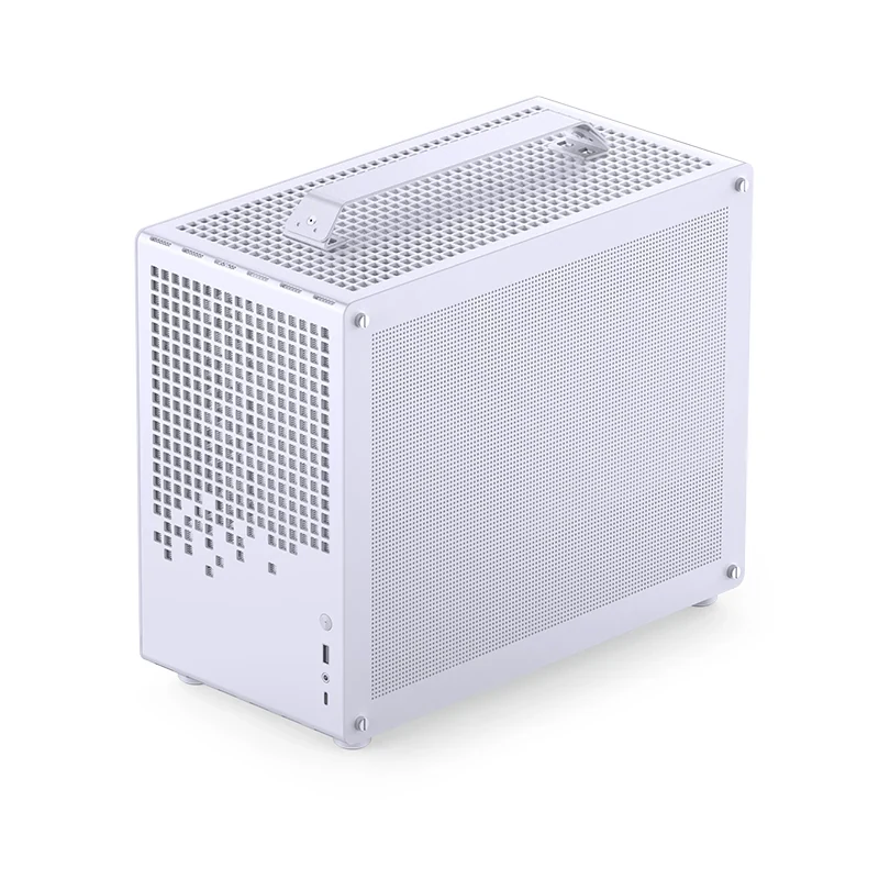
The opposite-side product view helps identify the actual chassis, handle and front connections. Jonsplus gives a body size of 370 × 186 × 295 mm, but the dimensions including handle, feet and other protrusions are 382 × 198 × 335 mm, in depth × width × height order. Use the assembled dimensions for the intended desktop or shelf, then allow for the real cable connections and access you need. The smaller body measurement is not the whole installed envelope.
Before checkout, your retained-parts plan should name the actual motherboard position, PSU body and mounting height, cooling branch, GPU length definition and thickness, storage arrangement and support choice. Confirm the accessory kit and front connections against that same plan. Keep the existing ATX PSU and AIO when their complete combination works; change the specific part or layout that fails, rather than replacing useful hardware because separate maximum specifications appeared contradictory.