The original Thermaltake Tower 500 can be a useful destination for an existing PC with several mechanical hard drives and a 360 mm liquid cooler. Its right-side mounting position has a crucial condition: the radiator’s complete body must fit a published 399 mm length limit. The “360” name describes the fan format, not the finished radiator length, so it cannot settle that purchase by itself.
Storage needs the same attention to the actual arrangement. Thermaltake depicts eight hard drives across rear and front mounting areas, but those areas also participate in cooling and graphics-card clearance decisions. Start with your exact retained drives and cooler, then decide which brackets, covers, fans and electrical connections the whole move requires.
Locate the Eight Hard Drives Instead of Adding Advertised Capacities
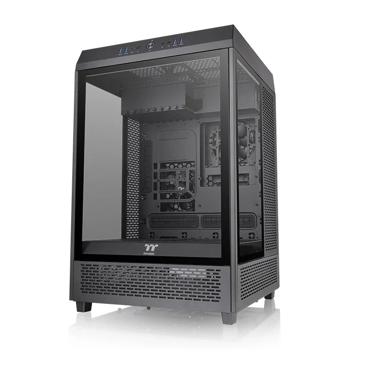
Check that the listing is for the original Tower 500, such as black model CA-1X1-00M1WN-00. This guide does not transfer its dimensions to the Tower 600, 300 or similarly named newer chassis. The original measures 608 × 388 × 398 mm, has nine expansion openings and uses three tempered-glass panels. Its desktop footprint is only one part of the space you need: leave access for the panels, top connections and rear storage compartment.
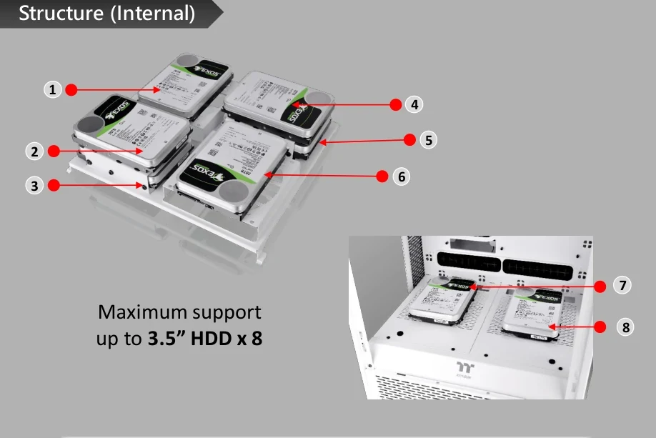
The numbered manufacturer illustration makes its eight-HDD arrangement more useful than a capacity figure. Positions 1–6 are stacked in two groups on the rear bracket; 7 and 8 sit on the front power-cover area. Eight disks therefore do not all disappear into a hidden rear cage. Two use space visible through the front glass, and the rear arrangement differs substantially from the factory photograph with two rear fans.
Use those two locations when checking your inventory. For each retained drive, record whether it is a 3.5-inch mechanical disk or a 2.5-inch SATA device, its connector location, and where its cable will leave the mounting area. Then assign an actual destination. A generic “supports eight drives” entry does not identify the needed brackets or demonstrate cable access around stacked disks.
The illustration establishes Thermaltake’s depicted arrangement, not a method for improvising a stack with loose drives or spacers. When buying a used chassis for a large drive collection, ask for photographs of the actual rear assembly, front covers and mounting fittings. If the package cannot reproduce the pictured retention hardware, do not price it as a complete eight-drive kit.
Separate the SSD Illustration from the Mixed-drive Headline
Thermaltake’s eight-SSD illustration uses another allocation: four SSDs on the front covers and four in the rear area. The two pictures show different storage choices, rather than two sets of positions you can automatically add together. Compare the pictured front area in particular: the space occupied by front HDDs in the eight-HDD arrangement is used differently for the SSD arrangement.
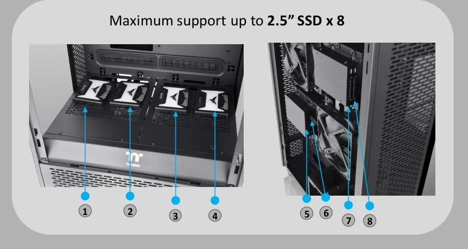
The current product page also advertises four HDDs plus eight SSDs. That is a manufacturer capacity claim, but the numbered presentation does not show a complete twelve-device installation. The manual’s individual bracket alternatives likewise should not be added without checking which face and mounting position each drive uses. If twelve simultaneous drives are essential to your move, obtain the exact combined allocation and required fittings before ordering; the eight-device pictures do not establish it.
| Your retained storage | Useful starting evidence | Purchase consequence |
|---|---|---|
| Several 3.5-inch HDDs | Numbered rear and front HDD locations | Identify complete mounting hardware and which cooling locations it consumes |
| Mainly 2.5-inch SATA SSDs | Four front plus four rear SSD illustration | Count the correct fittings and keep the front covers available |
| A smaller HDD/SSD mixture | Manual’s named bracket alternatives | Assign each device to a specific alternative before totaling it |
| Four HDDs and eight SSDs together | Product-page capacity claim without a complete pictured allocation | Require a combined mounting plan; do not infer it from separate maxima |
This distinction can prevent an unnecessary case change. Someone retaining four HDDs needs a valid four-drive arrangement with the chosen cooler; they do not need to assume that every advertised maximum can coexist. Someone retaining twelve SATA devices has a different unresolved requirement and should not accept an eight-device photograph as its answer.
Treat the Rear Drive Bracket and Rear Cooling as Shared Space
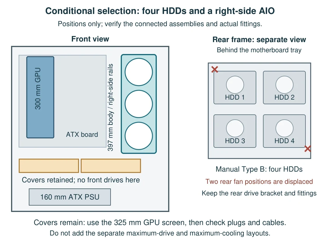
The manual names two rear-bracket arrangements. Type A carries two 3.5-inch HDDs plus four 2.5-inch devices; Type B carries four 3.5-inch HDDs. These are alternatives on the bracket, not six HDDs plus four SSDs obtained by adding the labels. The removal drawing places that bracket in the rear fan area, which makes its cooling relationship visible.
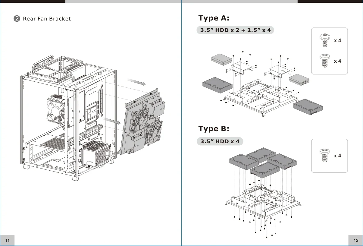
The original chassis includes two rear 120 mm fans. Do not carry their factory location into every storage plan automatically. The six stacked rear HDDs in the presentation occupy the space shown with fans in the factory arrangement, while other manufacturer photographs show a less densely populated bracket alongside the fans. Choose the actual drive arrangement first, then identify which fan positions remain available.
For a four-HDD move, the manual’s Type B arrangement is a concrete starting point. Inspect its bracket, screw locations and cable access rather than assuming the factory two-fan photograph is the same layout. If preserving both rear fans is a requirement, you need a different supported allocation of your drives; their presence in a separate marketing photograph does not resolve the conflict.
Use the manufacturer’s mounting sequence for the actual assembly. The guide shows removing the rear bracket before fastening drives and reinstalling it. Plan enough cable access to carry out that operation without pulling on the motherboard’s SATA sockets. Label the drives and their intended cables before moving them so the mechanical mounting plan and electrical inventory remain connected.
Decide What the Front Power Covers Are Doing
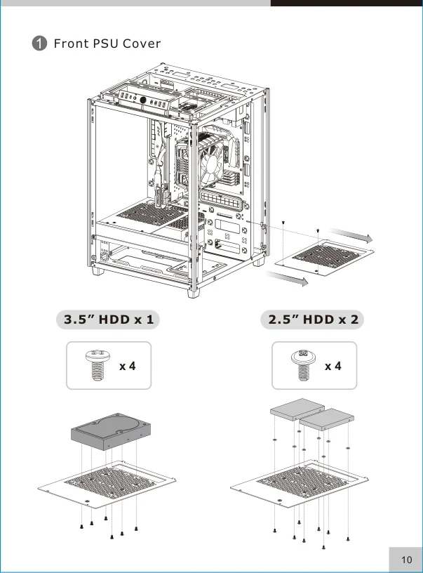
The front-cover drawing shows one HDD or two SSDs on a cover plate, with the corresponding fastening arrangement. The complete manufacturer storage pictures use more than one front position. Keep the actual cover count and their fittings in your purchase inventory; do not multiply one diagram into extra positions that are absent from the supplied chassis.
Compare the GPU Endpoints Before Removing the Covers
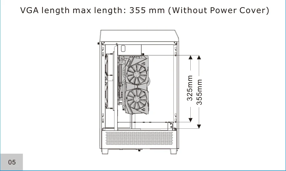
Those covers also affect the rest of the PC. The manual lists a GPU length limit of 325 mm with the power cover and 355 mm without it. If the covers hold your front drives, removing them to gain graphics-card length removes part of that storage plan. A 340 mm card cannot be approved by quoting 355 mm while silently retaining the front-cover drives.
Keep the Lower Cooling Bracket Distinct from the Drive Covers
The exploded fan view separates two power-cover pieces from the lower front and bottom brackets. Follow the actual part you intend to use rather than treating every fan symbol as an additional free mounting surface.
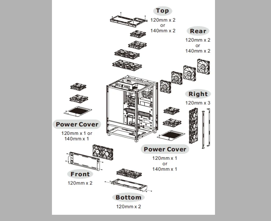
Cooling creates another choice in the same lower region. The product specification lists fan support on the power cover and a lower fan/radiator bracket that can be arranged vertically or horizontally. A cover holding a disk is not simultaneously an unobstructed fan mounting surface. Before adding bottom cooling to a multi-drive plan, compare the actual bracket orientation, drive locations, connectors and cable path.
For example, suppose two of your retained HDDs are assigned to the front covers. Keep those covers in the initial inventory, use the covered GPU limit, and leave lower cooling uncommitted until you have checked the occupied surfaces. This is more useful than selecting a maximum-length card, maximum lower radiator and maximum drive count independently.
Measure the Complete Side Radiator Before Calling It Compatible
The right-side bracket is the Tower 500’s dedicated route for a 360 mm AIO. Its mounting pattern accommodates a row of three 120 mm fans; a 360 mm name does not state the length of the radiator’s end tanks. Find the cooler manufacturer’s complete radiator drawing and compare its end-to-end dimension, not only the fan spacing.
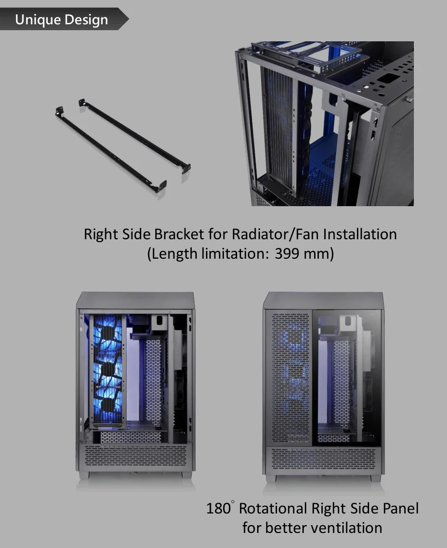
Thermaltake’s product prose says radiators under 399 mm, while its specification and installation guide use a 399 mm maximum. Because the boundary wording differs, use less than 399 mm for the first screening step and confirm an exact-399 mm candidate against the particular radiator and chassis revision. Do not silently choose the more permissive wording when the retained cooler sits exactly on the limit.
Compare the Outer Body with the Chassis Length Screen
The length diagram separates the chassis screen, the complete radiator body and the three-fan row. Its illustrative outer body is 397 mm long; the fan row is 360 mm. The end tanks belong inside the body measurement. The 2 mm difference from the nominal chassis screen is a length calculation, not a cable, thickness or screw-clearance allowance.
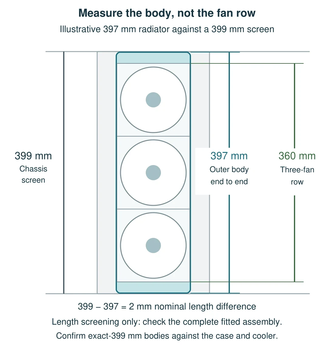
For example, a nominal 360 cooler with a documented 397 mm body clears the initial length screen. A nominal 360 model with a 402 mm body does not. A 399 mm body remains a boundary case requiring confirmation. These examples compare length only: none establishes that the fan stack, fittings, hoses and connected components fit together.
Next, examine the whole installed assembly. Record radiator thickness, fan thickness and whether there are fans on one or both sides; locate the hose fittings and the path to the CPU block. Check that the mounting screws suit that radiator and fan arrangement. A case’s radiator support is not permission to use an arbitrarily long screw through a thinner assembly.
Thermaltake describes a six-fan push-pull possibility at this position. Treat it as a layout option requiring the same complete checks, rather than assuming it remains available with every storage and motherboard combination. The top support list separately includes 240 and 280 mm radiators; it does not list a top 360. A 420 mm radiator is not an interchangeable substitute for the right-side 360 either.
Keep the Rail Seating and Upper Fastening Hardware Together
The installation drawing shows the two rails attached to the radiator assembly, the lower ends locating at the case base, and two upper fastening screws. Follow those relationships when checking a used kit: a loose radiator bracket photograph does not establish that the lower seating features or upper fastening parts are intact. The guide depicts panel reversal as a separate final step.
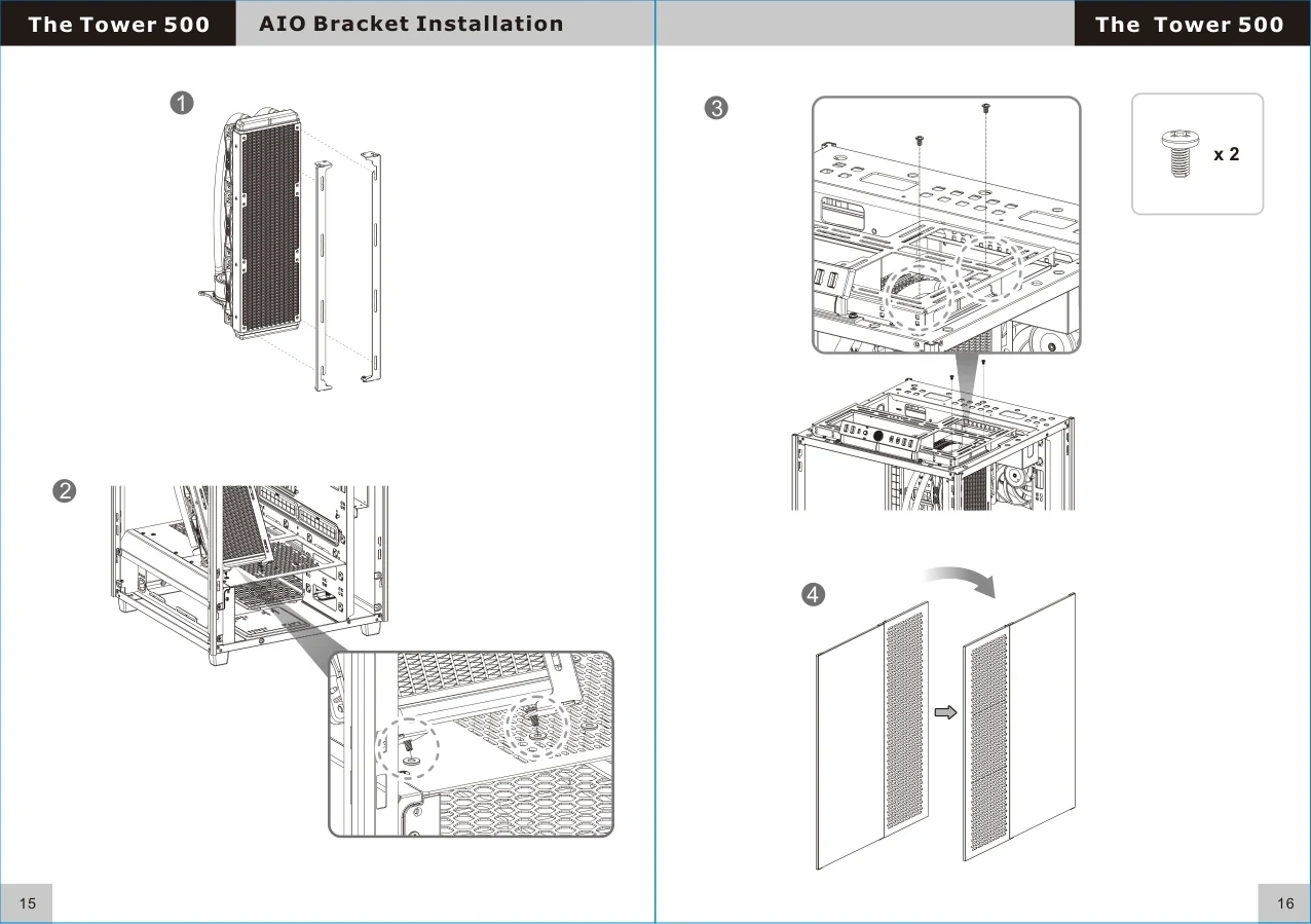
The original photographs also show the right panel rotated 180 degrees to place its mesh alongside the radiator area. Check that orientation when planning the side assembly and access to its fasteners. A visibly attractive glass view and the useful mesh position are not necessarily the same panel arrangement.
Check the Retained Board and Graphics Card with the Covers in Place
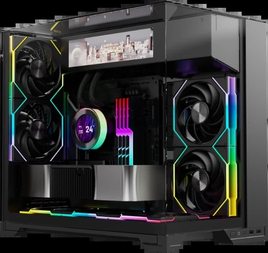
Use the graphics-card limit belonging to your chosen storage configuration: 325 mm with the cover, or 355 mm with it removed. Measure the complete card assembly and its connected power lead, and inspect the exit path around nearby hardware. The manufacturer’s RGB build is helpful for seeing the vertical arrangement, but it does not demonstrate the eight-HDD configuration or approve the dimensions of another GPU.
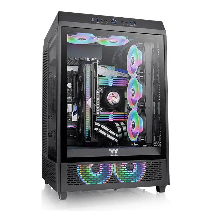
Motherboard width needs an exact-model check too. The current product page and presentation specify E-ATX up to 12 × 12 inches. The manual’s specification additionally lists CEB and 13 × 12-inch EEB, and its diagram associates EEB with removing the power cover. Those statements should not become a blanket promise that any wide board fits while all front drives remain.
For an ordinary retained ATX board, check its mounting holes, accessible cable sockets and the right-side cooling assembly. For a wider board, obtain its actual dimensions and compare them with the particular chassis layout before purchase. “E-ATX” on both boxes is insufficient when the drive-carrying cover, motherboard edge and radiator need the same working space.
The case’s nine expansion openings are also separate from a GPU riser package. Inventory the mounting arrangement you actually intend to use; do not assume that a case photograph supplies an optional adapter or that moving the card changes all the stated length conditions.
Keep the PSU, SATA Cables and Case Fittings in One Inventory
The Tower 500 uses a standard PS2-format PSU purchased separately. The manual’s specification gives a 200 mm PSU limit, while another warning drawing labels 300 mm without clearly tying that larger number to a complete retained-drive and bracket configuration. Use the 200 mm specification for initial selection and include the modular plugs and cable bends in the space check; do not treat the unexplained 300 mm label as general approval for a longer unit.
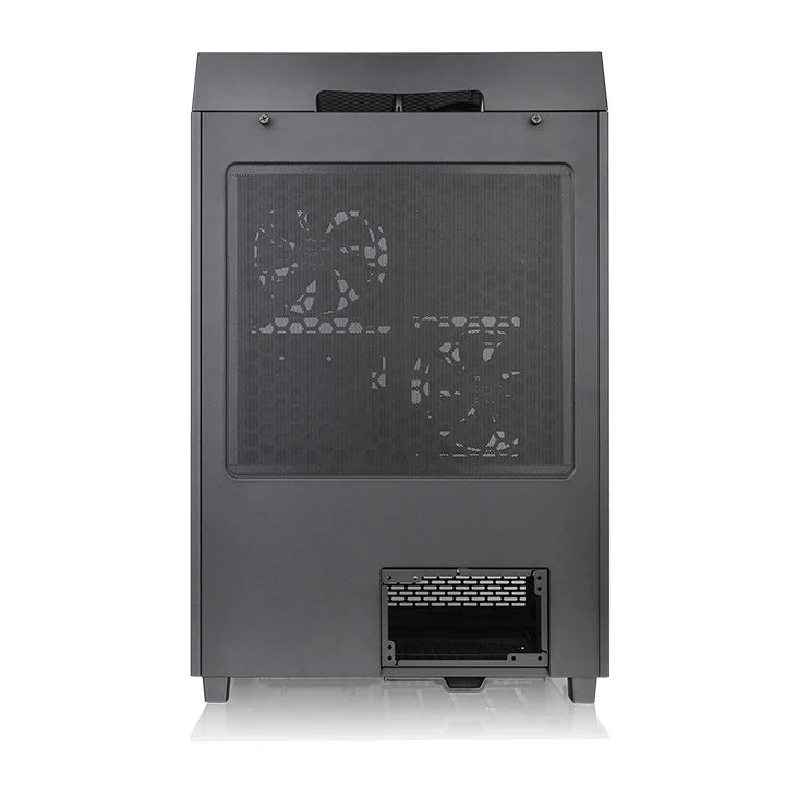
The rear photograph shows the lower PSU opening separately from the upper rear fan/drive area. Trace the SATA power leads from that lower location to every planned disk. Use only cables compatible with the exact modular PSU. A collection of physically similar plugs from the old and replacement units is not a safe substitute for the matching harness.
Each retained SATA drive needs a motherboard/controller data connection and a suitable PSU power connection. Count these for the actual drive total, including any SATA SSDs, before buying the case. Eight mounting positions do not add SATA ports to the motherboard. Conversely, having eight motherboard ports does not supply the missing drive brackets.
| Item to retain or obtain | What to confirm before purchase |
|---|---|
| Rear drive bracket and front covers | Correct pieces for the intended drive arrangement, with their fastening hardware |
| HDD and SSD fittings | Matching screws and the specified rubber parts or pads for the chosen positions |
| Right-side radiator bracket | Both bracket pieces and their fasteners, plus the cooler’s own suitable screws |
| PSU and original compatible harness | Body, plugs and cable access fit the selected lower layout |
| SATA data and power connections | One complete route for each installed SATA device |
| Fan and pump connections | Motherboard or approved controller connections for the actual retained cooler and case fans |
The original manual’s accessory inventory includes drive screws, HDD rubber fittings, SSD pads and two AIO bracket pieces. For a used chassis, compare the seller’s actual hardware with the positions you will use; a bag of unidentified screws is not evidence that every pictured storage configuration can be assembled.
Check the Top Connections Before Moving the Motherboard
The top-panel detail shows four USB Type-A sockets, one USB Type-C socket and separate audio connections. Thermaltake identifies these as four USB 3.0 ports and one USB 3.2 Gen 2 Type-C port. The pictured Snow chassis has the same listed connector arrangement as the black version.
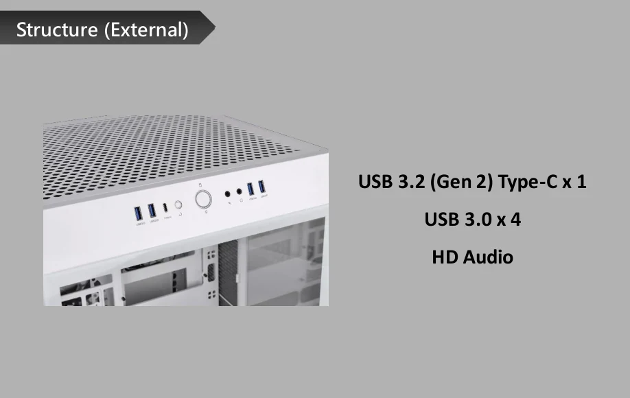
Confirm that the retained motherboard has the corresponding internal connections for the case leads, together with the appropriate audio and front-panel connections. Use the motherboard’s own header labels and manual rather than guessing from the external socket shape. If the board cannot serve every case connector, identify which front function would be lost before counting the migration as complete.
The optional 3.9-inch display kit is a separate accessory. It is not required to keep the disks or install the side radiator, and its appearance in a display build does not mean a second-hand case includes it. Keep that optional purchase outside the essential retained-parts budget unless you specifically want the display.
Choose a Complete Configuration Before Buying the Shell
For example, a move retaining four HDDs, a 300 mm graphics card, a conventional ATX board, a 160 mm ATX PSU and a 397 mm-long 360 AIO has useful starting routes. The manual’s Type B rear arrangement identifies the four-HDD destination; the card falls within the covered length screen; and the radiator passes the conservative length screen. You still need to verify the occupied rear fan positions, exact bracket kit, radiator stack, hoses and every electrical connection. The individual dimensions are screening results, not a completed assembly certificate.
Now consider eight HDDs and a 340 mm card. The numbered HDD picture assigns two disks to the front covers, while the longer-card clearance depends on removing the cover. Those two choices cannot simply be combined. Change the retained hardware or obtain a different complete supported allocation before ordering, rather than assuming that spare advertised capacity will solve the conflict.
The useful Tower 500 purchase is the package that preserves your particular drives and cooler with a clear mounting map, compatible GPU and board space, correct PSU harness and complete fittings. Start with the drive destinations, screen the full side-radiator length, and carry each shared bracket or cover decision through the rest of the inventory.