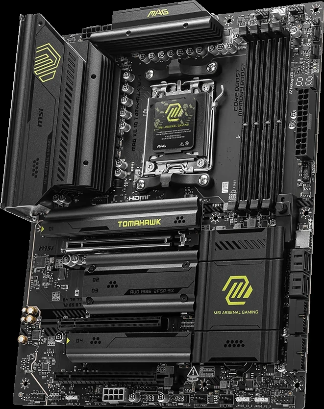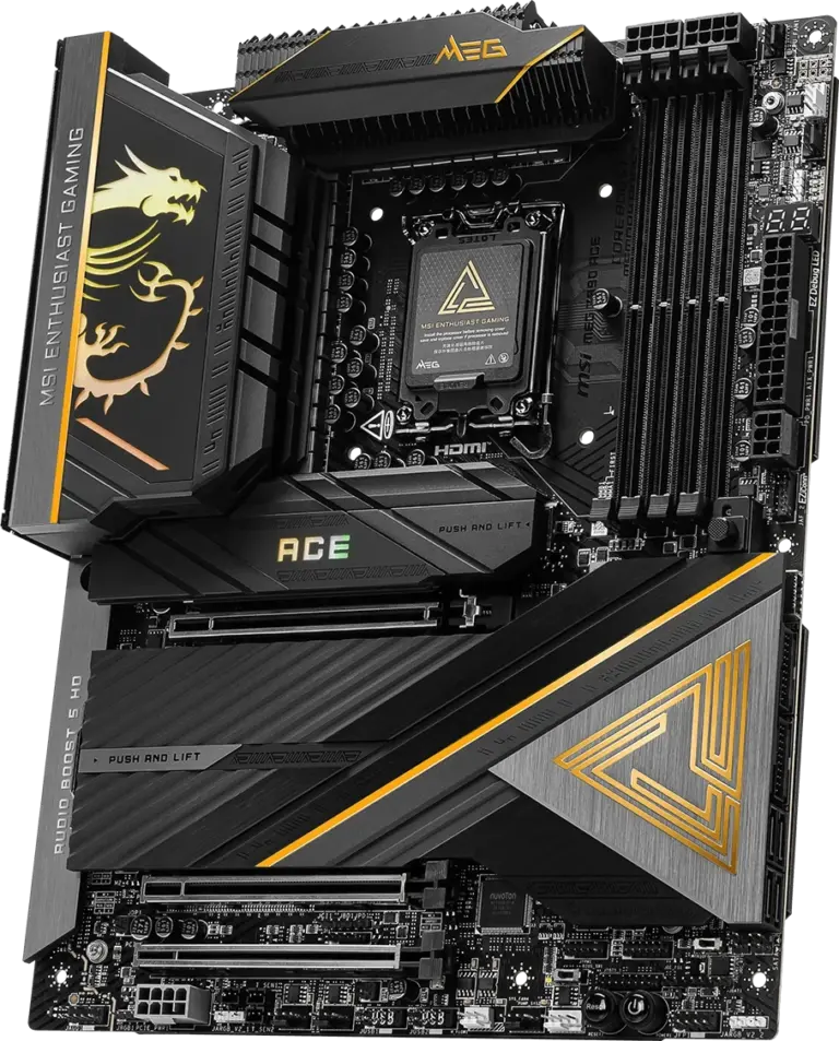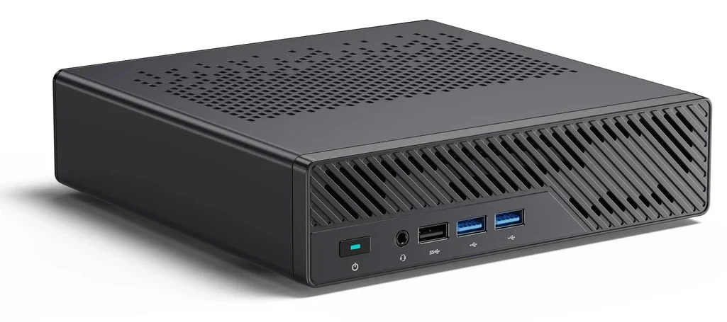
An existing AM5 processor can be a starting point for a MINISFORUM MS-A1 build, but it does not define a complete reusable parts bundle. The CPU architecture changes the SSD connection map and rear Type-C capability. Desktop DDR5 modules are also the wrong format for its two SODIMM sockets, and the machine needs its specified external power arrangement and compact cooling hardware.
Start with the exact CPU, MS-A1 version and supplied accessories. Then assign each retained NVMe drive to a numbered position. This matters particularly with the Ryzen 5 8500G: the V2 manual's Phoenix2 row leaves one position unsupported and changes the other connections. “Four M.2 positions” does not mean four equally fast, usable drives with every AM5 CPU.
Check the CPU and the no-CPU Package Together
The V2 manual groups processors by architecture, giving these examples: Raphael includes 7600/7900; Granite Ridge includes 9950X/9900X/9600X; Phoenix includes 8700G/8600G; and Phoenix2 includes 8500G. Use the exact processor's architecture when reading the storage matrix. Do not group every Ryzen 8000G chip into one identical configuration.
Those examples explain the connection map; they are not a substitute for confirming that the particular MS-A1 hardware, BIOS and cooling configuration supports the CPU you intend to retain. Establish that combination before ordering a no-CPU unit. Do not infer a universal power limit or cooling result from an older review of another configuration.
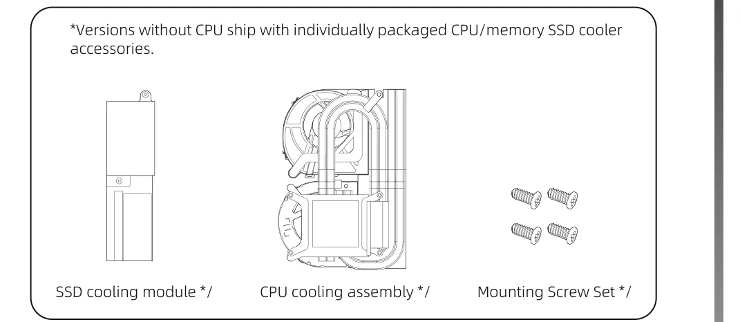
The barebone package also needs checking as a set of physical parts. The original manual identifies the CPU cooling assembly, SSD cooling module and mounting screw set as separately packaged accessories for versions without a CPU. The illustration shows the shapes to look for: a slim SSD cooling plate, the compact CPU cooling assembly and its mounting hardware. An empty CPU socket does not mean those pieces are optional to the finished build.
Ask what is included in the actual offer, especially with an opened or incomplete package. Retaining a tower CPU does not establish that its old cooler can replace the MS-A1 assembly. The useful purchase comparison includes the correct cooling parts and fasteners, not just the chassis price.
DDR5 Desktop Memory Does Not Become SODIMM Memory
The manufacturer's specification lists two DDR5 SODIMM sockets, up to 96GB total, with no ECC memory support. A tower's full-size desktop DDR5 UDIMMs should not be counted as reusable merely because both systems say DDR5. Include a suitable SODIMM kit in the purchase group if that is the memory you are starting with.
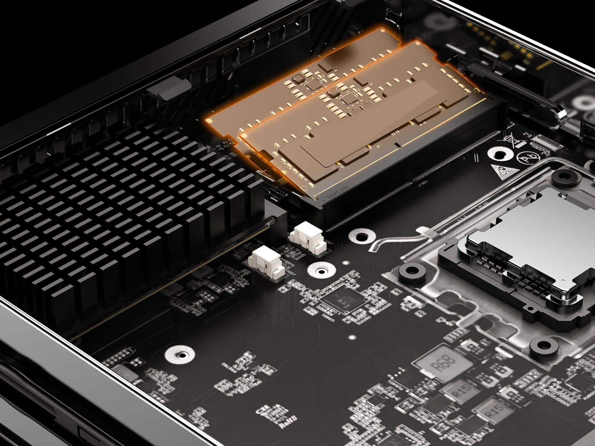
The manufacturer's memory illustration places the compact modules beside the AM5 socket. It helps distinguish the internal arrangement from a conventional desktop motherboard, but it does not establish that an arbitrary SODIMM kit will run at its advertised settings.
If you already own DDR5 SODIMMs, check the exact modules and supported configuration before retaining them. Count sockets as well as capacity: four modules cannot all fit into two positions. Choose the required working capacity first, then confirm the kit and settings for the actual CPU and firmware. The 96GB system limit is not a promise for every memory combination.
Assign SSDs Using the Architecture Row
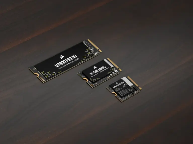
All M.2 storage positions in the V2 manual are for NVMe SSDs. The manual explicitly excludes SATA-protocol SSDs and warns that inserting the wrong protocol may damage the drive. A retained 2280 SATA M.2 drive is therefore not a candidate just because it shares the length and connector form with a 2280 NVMe SSD.
Use the manual's position numbers 1–4 for the following allocation:
| Position | Raphael / Granite Ridge / Phoenix | Phoenix2, such as 8500G |
|---|---|---|
| 1 | PCIe Gen3 x4 | PCIe Gen4 x2 |
| 2 | PCIe Gen4 x1 | PCIe Gen4 x4 |
| 3 | PCIe Gen4 x4 | Not supported |
| 4 | PCIe Gen4 x4 | PCIe Gen4 x1 |
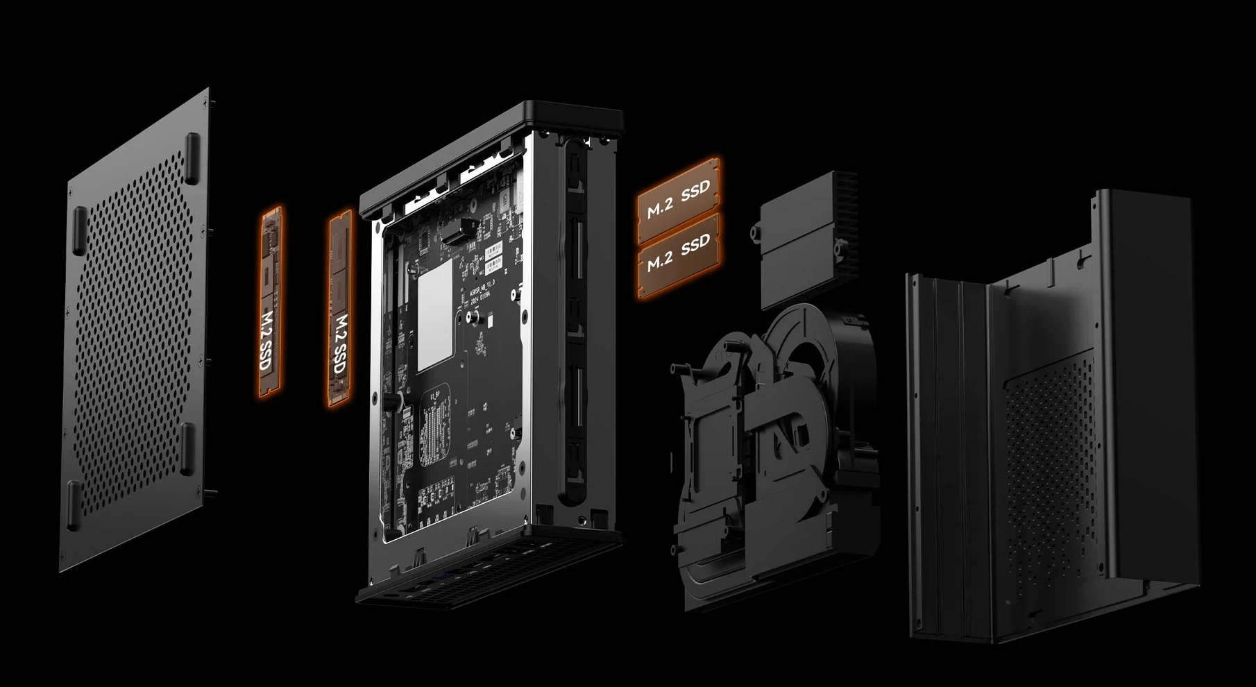
The rows come from the V2 manual's numbered matrix, not from treating the four visible positions as interchangeable. The exploded storage illustration shows the two-sided packaging, while the matrix establishes which connections are available with the selected CPU.
For Raphael, Granite Ridge and Phoenix, all four positions are listed, but position 2 has a Gen4 x1 link and position 1 a Gen3 x4 link. That is a different arrangement from four Gen4 x4 connections. For Phoenix2, position 2 becomes Gen4 x4, position 1 is Gen4 x2, position 4 is Gen4 x1 and position 3 is unavailable.
For example, if a build must retain four separate NVMe SSDs, the 8500G row does not meet that requirement natively. You need to change the retained-drive plan or reconsider the CPU/system combination. Buying a fourth SSD or choosing a faster drive cannot make the unsupported position active.
If only two SSDs are moving, allocate them deliberately. The Raphael/Granite Ridge/Phoenix row provides Gen4 x4 connections at positions 3 and 4. Phoenix2 instead provides its Gen4 x4 connection at position 2. These are starting points for selecting positions, subject to the actual drives and assembly; they are not measured workload results or a universal boot-drive rule.
The product page's broad “four PCIe 4.0” wording should not replace this matrix. It also qualifies four-drive support by architecture. Use the precise row when deciding what can stay.
Find the Numbered Positions Before Fitting the Cooling Plates
The original installation diagram places positions 1 and 2 on the CPU side, with positions 3 and 4 on the back side. Follow those views when matching the table to the hardware. Do not mirror the back-side drawing onto the CPU-side view or assume numbers from another motherboard apply here.
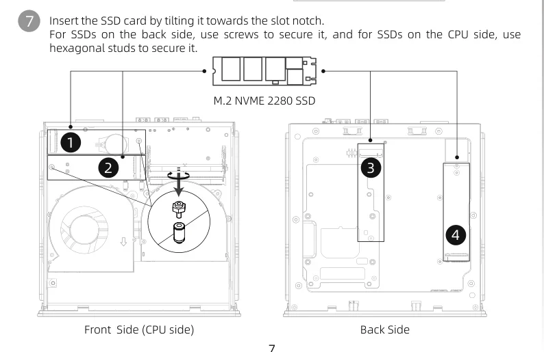
The diagram also identifies 2280 NVMe drives and the mounting arrangement. The manual distinguishes screws for the back-side SSDs from hexagonal studs on the CPU side. It separately shows fitting the SSD cooling pieces and retaining straps, then reinstalling the cooling module before sliding the board assembly back into the case.
Count those parts while access is available. An SSD being the correct protocol and length does not prove that its existing oversized heatsink fits under the MS-A1 cooling arrangement. Compare the actual drive, cooling plate and mounting hardware instead of assuming a tower installation transfers unchanged.
Disconnect power before handling internal parts. The manual notes that current can remain present when the system is off and instructs users to unplug power for the relevant handling. It also warns about stripping CPU-side SSD screws. Keep the correct tools and fasteners with the build rather than forcing a mismatched screw into place.
Check the Relevant Slot’s M.2 Mode Switch
The V2 manual shows a switch beside the relevant storage position with ON U.2 and ON M.2 directions. For an M.2 drive in that position, it requires the switch to be set to ON M.2, warning that an incorrect setting may damage the drive. Include that check in the installation plan before applying power.
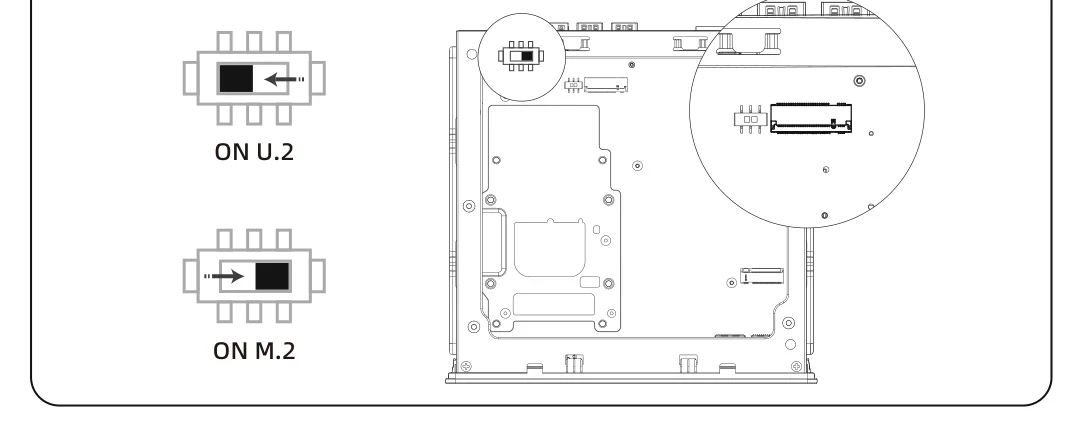
Use the illustrated location and label on the actual board. The switch check is separate from the CPU matrix: selecting M.2 mode does not enable Phoenix2's unsupported position or widen a CPU-limited link. Both the correct mode and an available, compatible position are required.
For this retained-NVMe build, there is no need to turn the U.2 alternative into a separate storage project. The practical requirement is to verify the M.2 setting, keep the right mounting parts and follow the model's assembly instructions.
Rear Type-C Needs the Right CPU and Controller Firmware
The rear hardware view locates Type-C between HDMI and the blue Type-A port. OCuLink and the round DC input are farther to the right. Their physical proximity does not make them the same expansion or power connection.
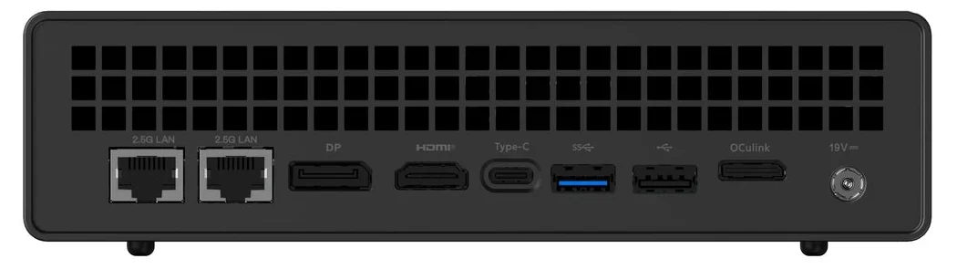
The manual specifies the rear Type-C modes as follows:
| Architecture described | USB capability | Display provision |
|---|---|---|
| Raphael / Granite Ridge | USB 3.2, up to 10 Gb/s | DisplayPort Alt Mode |
| Phoenix / PHX | USB4, up to 40 Gb/s; USB3 up to 10 Gb/s | DisplayPort Alt Mode |
A retained Raphael or Granite Ridge CPU therefore should not be purchased around an assumed USB4 connection. A USB4 label on a general product illustration does not override the CPU condition. The Phoenix2 storage row also is not, by itself, confirmation of the 8500G's Type-C mode: if USB4 is essential with that exact CPU, obtain confirmation for the specific unit and firmware before committing.
There is a second dependency beyond the CPU. The manual says different architectures require different Type-C controller firmware, otherwise the interface may not work correctly. The current MS-A1 support block provides separate packages labelled for 7000–9000 and 8000G. Match the package and instructions to the actual CPU and hardware; do not treat the main BIOS update alone as proof that the controller configuration is correct.
If changing CPU architecture later, revisit both the SSD map and controller firmware. A working Type-C port before the swap does not establish the same capability afterwards. Device and cable support still matter; the listed link modes are not guaranteed file-copy speeds.
OCuLink is a separate external PCIe expansion path, listed in the manual at up to PCIe 4.0 x4 and requiring specialized expansion hardware. If keeping a desktop graphics card depends on that route, include the actual external equipment and its compatibility in the purchase plan. Plan OCuLink attachment changes with the system powered off and follow the external equipment’s instructions. The manual specifically requires disconnection with power off and warns of damage otherwise; do not plan to unplug it while running.
Retain the CPU and Drives Without Losing the Rest of the Budget
The specification lists a 19V/12.63A external adapter, and the manual requires 19V DC input. Use the appropriate supplied or manufacturer-confirmed adapter for the exact unit, with the correct connection and regional power cord. A tower ATX supply or an arbitrary brick with a similar plug is not a verified replacement. The rear Type-C port is not the specified DC power input.
| Existing item | Retention decision | Include in the purchase plan |
|---|---|---|
| AM5 CPU | Confirm exact unit, BIOS and cooling support | Architecture-dependent SSD and Type-C plan |
| Desktop DDR5 UDIMMs | Wrong specified memory format | Suitable two-module SODIMM configuration |
| 2280 NVMe SSDs | Match each to an available numbered position | Cooling plates, studs, screws and straps |
| SATA M.2 SSD | Excluded by the NVMe-only requirement | A different storage plan |
| Tower cooler and PSU | Do not assume they replace MS-A1 parts | Correct cooling assembly and 19V adapter |
For example, a supported 7600-based plan with two suitable NVMe SSDs still needs SODIMMs if the old machine uses desktop memory, the complete cooling kit, the specified adapter and a Type-C plan based on 10 Gb/s rather than USB4. A plan retaining an 8500G and four NVMe SSDs has a different obstacle: one storage position is unavailable before memory or accessory costs are considered.
Make the keep-or-replace list for the whole machine before ordering. The AM5 socket can preserve a valuable CPU, but the useful MS-A1 configuration is the one whose storage positions, memory, firmware, cooling and power arrangement all match the parts you actually intend to keep.