As an Amazon Associate I earn from qualifying purchases.
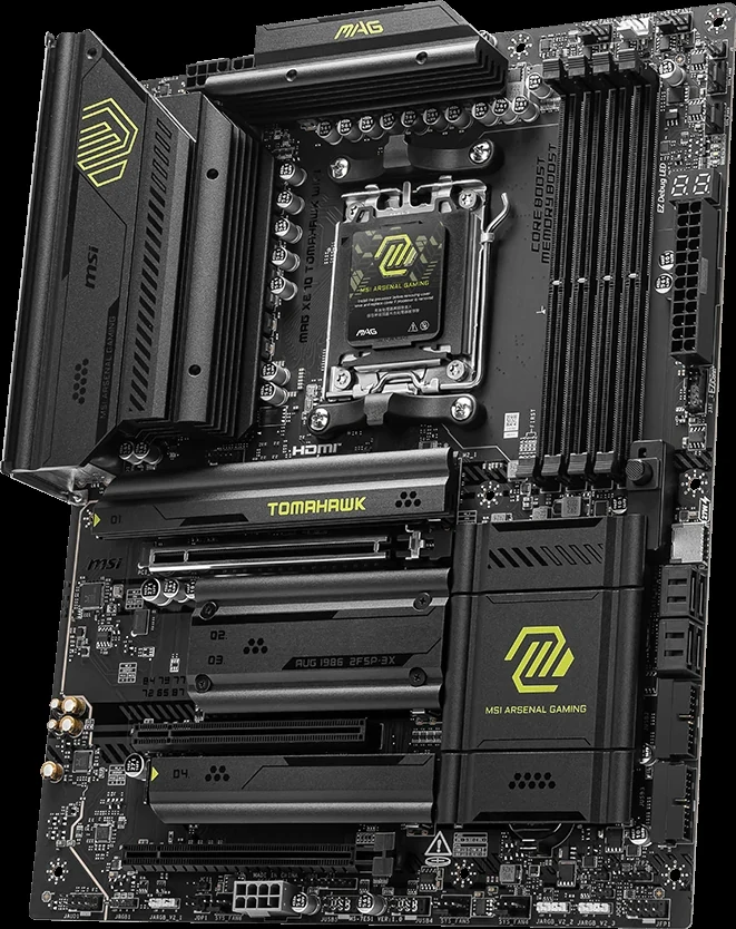
The MSI MAG X870 TOMAHAWK WIFI can accommodate four M.2 devices, but that does not mean four unrestricted x4 SSD links alongside full lower-slot bandwidth. M2_2 shares resources with the rear USB4 connection, and M2_3 changes PCI_E3 from x4 to x2. If the lower card truly needs x4, the board's BIOS option restores it by disabling M2_3. Your CPU also changes which slots are available and their generation.
Plan this board as two separate resource decisions plus a CPU check. That produces a usable storage and expansion layout before you buy the fourth SSD or a card whose required link width the finished build cannot provide.
Start with the Exact CPU Branch
MSI lists the following differences for the primary GPU slot and CPU-connected M.2 slots. These apply to the MAG X870 TOMAHAWK WIFI, not every X870 board.
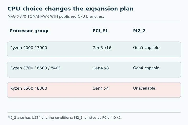
| Processor group | PCI_E1 graphics slot | M2_1 | M2_2 |
|---|---|---|---|
| Ryzen 9000 / 7000 | Up to PCIe 5.0 x16 | Up to PCIe 5.0 x4 | Gen5-capable, subject to USB4 sharing |
| Ryzen 8700 / 8600 / 8400 | Up to PCIe 4.0 x8 | Up to PCIe 4.0 x4 | Gen4-capable, verify sharing behavior for CPU/BIOS |
| Ryzen 8500 / 8300 | Up to PCIe 4.0 x4 | Up to PCIe 4.0 x4 | Unavailable |
The 8500/8300 branch rules out the four-onboard-M.2 plan immediately because M2_2 is unavailable. Do not order a fourth onboard SSD on the assumption that the board's four physical sockets override that CPU limitation.
For the 8700/8600/8400 branch, do not copy a Gen5 lane calculation from a Ryzen 9000/7000 example. MSI states that the CPU-connected M.2 slots fall to Gen4 with Ryzen 8000. Confirm the available sharing modes for the exact CPU and current BIOS if the plan depends on a particular M2_2 bandwidth allocation.
Assign Drives by Interface, Length, and Slot Role
| Slot | Connection source | Listed maximum | Supported device lengths |
|---|---|---|---|
| M2_1 | CPU | PCIe 5.0 x4 with supporting CPU | 2280 / 22110 |
| M2_2 | CPU | PCIe 5.0 x4 before sharing conditions | 2260 / 2280 |
| M2_3 | Chipset | PCIe 4.0 x2 | 2260 / 2280 |
| M2_4 | Chipset | PCIe 4.0 x4 | 2260 / 2280 |
The CPU exceptions and sharing rules qualify these maxima. In particular, M2_3 is listed as x2: it is not a fourth full-width x4 SSD connection waiting to be unlocked without consequences.
Match the intended SSD's dimensions and the manual's heatsink restrictions before assigning it. A 22110 drive has a listed length route in M2_1; that does not make it suitable for M2_2, M2_3, or M2_4. The slots in this table specify PCIe support; do not infer M.2 SATA support from their shape.
For a Ryzen 9000/7000 build with no special reason to do otherwise, a useful planning approach is to allocate M2_1 and M2_4 first. This is an editorial starting point based on the listed sharing rules, not a claim that MSI requires a particular boot-drive slot. It leaves the two conditional positions for deliberate decisions.
Decision One: M2_2 or Unrestricted USB4 Resources
MSI says the rear USB 40Gbps Type-C ports and M2_2 share PCIe 5.0 x4 bandwidth. With a device in M2_2, the published sharing mode divides that upstream allocation into x2 paths. A BIOS option gives M2_2 the x4 allocation while disabling the rear USB 40Gbps Type-C ports. The USB4 host controller itself supports up to PCIe 4.0 x4.
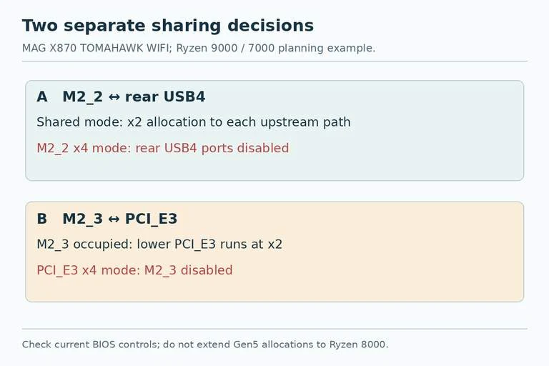
Keep the controller connection distinct from each external USB port's advertised signaling rate. An upstream lane split does not mean you should relabel a port “20Gbps,” nor does the 40Gbps label guarantee independent maximum transfers from both ports alongside the SSD. The useful purchase fact is the shared resource and the explicit BIOS tradeoff.
If rear USB4 is essential for your dock or external storage, preserve the USB4-enabled mode and accept the documented sharing condition when using M2_2. If the M2_2 drive's x4 allocation is essential, accept that choosing that BIOS mode removes those USB4 ports. A cable or a faster SSD cannot remove this board-level choice.
Decision Two: M2_3 or X4 for the Lower Card
PCI_E3 is the lower slot listed as PCIe 4.0 up to x4 from the chipset. Installing a device in M2_3 changes PCI_E3 to x2. MSI provides a BIOS option to restore PCI_E3 to x4, but that disables M2_3.
First determine whether the add-in card requires x4 operation or merely has an x4 connector. Consult its specification for supported link widths and the bandwidth needed for your workload. Do not assume every x4 card operates correctly or adequately at x2.
The other long physical slot, PCI_E2, is only PCIe 3.0 x1 electrically. Moving a card there is not an equivalent x4 workaround. Also check physical access: a thick graphics card or vertical mounting assembly can obstruct a lower slot even when the electrical plan works.
Choose One Complete Layout
For Ryzen 9000/7000, the following plans make the two sharing choices explicit. “Available” does not promise simultaneous maximum throughput from every connected device.
| Intended result | M.2 population | USB4 choice | PCI_E3 outcome |
|---|---|---|---|
| Four onboard SSDs, USB4 retained | M2_1, M2_2, M2_3, M2_4 | Shared mode | x2 with M2_3 occupied |
| Three onboard SSDs, lower card needs x4 | M2_1, M2_2, M2_4 | Shared mode if USB4 retained | x4 mode; M2_3 disabled |
| Two onboard SSDs, USB4 and lower x4 prioritized | M2_1, M2_4 | USB4 retained; M2_2 empty | x4; verify BIOS configuration |
| M2_2 x4 prioritized, lower x4 also needed | M2_1, M2_2, M2_4 | USB4 ports disabled | x4 mode; M2_3 disabled |
For example, a build with four 2280 SSDs, a USB4 dock, and a lower card that explicitly requires x4 does not meet all three requirements through these onboard positions. Keeping M2_3 populated prevents the requested x4 allocation to PCI_E3. Remove that SSD from the onboard plan, change the card requirement, or choose a different platform arrangement before buying the parts.
If the card supports x2 and its workload fits that connection, the first row can remain a candidate. That is a decision about the card and workload, not a guarantee supplied by the motherboard's physical slot length.
Verify the Configuration After Assembly
Before ordering, record the CPU, board model, intended BIOS modes, each SSD's slot, the add-in card's required link width, and the USB4 devices you need. Check the current manual for the BIOS controls and SSD heatsink restrictions. Avoid guessing menu names from another MSI board.
After assembly, confirm all expected drives are detected, the lower slot negotiates the intended link, and the required USB4 devices remain available. If using the rear Type-C ports for video, MSI also requires a processor with integrated graphics; a discrete graphics card does not erase that condition.
Four M.2 sockets describe the available positions. A successful expansion plan specifies the CPU branch and both sharing decisions, so the fourth SSD does not silently consume the bandwidth or port function another purchase depends on.