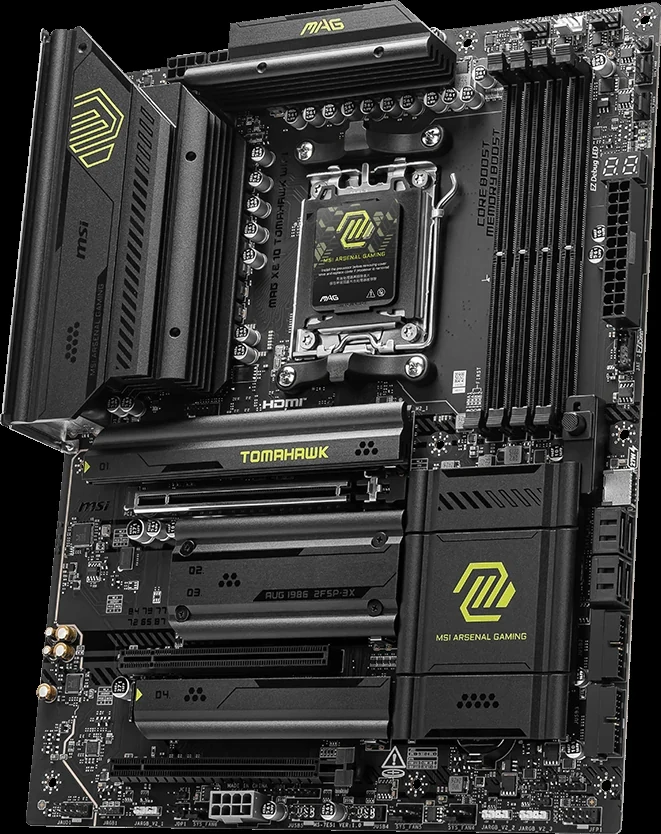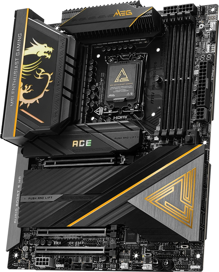
For five onboard M.2 drives, shortlist the MEG Z890 ACE or MPG Z890 CARBON WIFI. The MAG Z890 TOMAHAWK WIFI has four. ACE adds a consequential choice: switching M2_4 to CPU-connected Gen5 reduces PCI_E2 to x4. Leaving M2_4 on its default chipset Gen4 route preserves ACE's documented x8 second-slot arrangement.
The right purchase therefore starts with the expansion card you intend to keep. Write down its required electrical link, each SSD's protocol and length, and the graphics card's occupied slots. A five-drive specification alone cannot answer whether that complete set works together.
These are the Intel Z890 versions. The real board views identify the hardware; the slot drawings help locate connections hidden beneath covers.
Start with the Second Card’s Link, Then Choose ACE’s Lane Mode
ACE's PCI_E1 and PCI_E2 connect to the CPU, with individual Gen5 ceilings of x16 and x8. PCI_E3 is chipset-connected Gen4 x4. Installing a card in PCI_E2 reduces PCI_E1 to x8; using CPU Gen5 for M2_4 leaves PCI_E2 at x4.
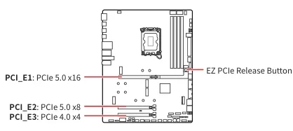
That distinction matters more than the three connectors' similar lengths. An x8 capture or networking card needs a different allocation from a card whose intended operation requires only x4. Check the retained card's documentation rather than treating its physical connector as its complete bandwidth requirement.
ACE's six CPU-lane modes are transposed below. Slot links are Gen5; M2_4's default chipset route is Gen4.
| PCI_E1 lanes | PCI_E2 lanes | M2_4 route |
|---|---|---|
| x16 | No signal | Chipset Gen4 x4 |
| x8 + x8 | No signal | Chipset Gen4 x4 |
| x8 + x4 + x4 | No signal | Chipset Gen4 x4 |
| x8 | x8 | Chipset Gen4 x4 |
| x8 | x4 + x4 | Chipset Gen4 x4 |
| x8 | x4 | CPU Gen5 x4 |
Plus signs mean bifurcation within one physical slot. The manual's “N/A” means M2_4 uses chipset Gen4, not that it is disabled.
For a conventional GPU plus one retained card, focus first on the last three rows. The bifurcated second-slot row matters only if your actual adapter requires that arrangement. Do not select it merely because two smaller numbers appear to add up to the width you want: the adapter and devices must match the selected mode.
For example, suppose your second card needs an x8 link. ACE's x8/x8 arrangement is the relevant starting point, with M2_4 left on chipset Gen4. Selecting the CPU Gen5 route for that SSD would sacrifice the required second-card width. A slot that still accepts the card physically would not preserve your stated x8 requirement.
Allocate All Five ACE Drives Before Promoting M2_4 to Gen5
ACE's onboard storage map is below. Length codes are M.2 sizes: 2280, for example, identifies a nominal 22mm-wide, 80mm-long module. Match each drive's actual protocol as well as its outline.
| ACE position | Connection and protocol | Supported lengths |
|---|---|---|
| M2_1 | CPU Gen5 x4, PCIe | 2260, 2280 |
| M2_2 | CPU Gen4 x4, PCIe | 2260, 2280 |
| M2_3 | Chipset Gen4 x4, PCIe | 2260, 2280 |
| M2_4 | Chipset Gen4 x4; optional CPU Gen5 x4, PCIe | 2260, 2280, 22110 |
| M2_5 | Chipset Gen4 x4, PCIe; also SATA | 2280, 22110 |
M2_4 defaults to chipset Gen4. Its CPU Gen5 route requires manual BIOS selection.
Keeping five drives does not inherently require making that change. Start by assigning the drive for which a Gen5 connection actually matters to M2_1. Then ask whether another drive needs the optional route enough to justify reducing the second card's link. Owning two Gen5-capable SSDs does not, by itself, establish that the second one is more important than the retained expansion card.
Keep the allocation sheet specific. “Five NVMe drives” leaves out lengths; “five M.2 drives” also leaves out protocol. Recording each drive's model, size and intended position exposes a mismatch before you purchase the motherboard or dismantle the old machine.
Carbon Offers Five Positions, with a CPU-slot Condition to Resolve
Carbon also has five onboard M.2 positions. Its M2_4 is chipset Gen4; the published storage map does not offer ACE's optional CPU Gen5 route there. M2_1 is its Gen5 position.
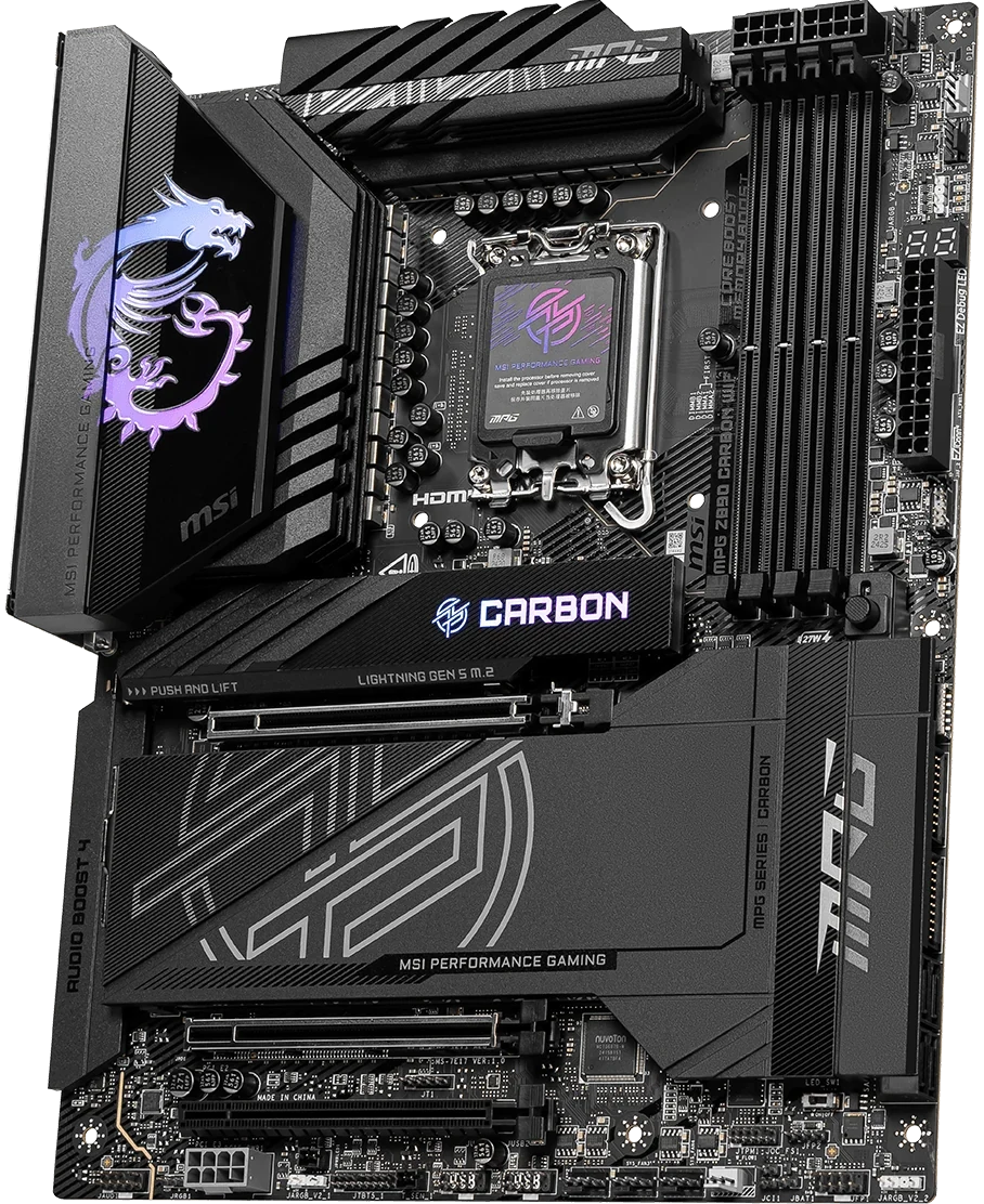
| Carbon position | Connection and protocol | Supported lengths |
|---|---|---|
| M2_1 | CPU Gen5 x4, PCIe | 2260, 2280 |
| M2_2 | CPU Gen4 x4, PCIe | 2260, 2280 |
| M2_3 | Chipset Gen4 x4, PCIe | 2260, 2280 |
| M2_4 | Chipset Gen4 x4, PCIe | 2260, 2280, 22110 |
| M2_5 | Chipset Gen4 x4, PCIe; also SATA | 2260, 2280 |
Its PCI_E1 and PCI_E2 are CPU-connected, individually listed up to Gen5 x16 and x8; PCI_E3 is chipset Gen4 x4. Those maxima do not establish a simultaneous x16/x8 configuration.
For a purchase that depends on a guaranteed x8 second-card link alongside a GPU, obtain the exact concurrent lane arrangement from MSI for your configuration. The reviewed Carbon specification and expansion-slot manual page do not provide the equivalent of ACE's six-mode table. Do not copy ACE's matrix onto Carbon simply because the two boards list similar slot ceilings.
This leaves Carbon as a five-drive candidate with a specific question to resolve, rather than proving that it fails the build. Give support the intended PCI_E1 and PCI_E2 devices and every occupied M.2 position. An answer about one empty slot's maximum width would not answer your combined configuration.
Tomahawk Suits Four Onboard Drives and a Suitable x4 Card
Tomahawk's PCI_E1 is CPU Gen5 x16. Both lower long slots, PCI_E2 and PCI_E3, are chipset Gen4 x4. Neither is a CPU-connected x8 alternative. Its four M.2 positions have the following assignments.
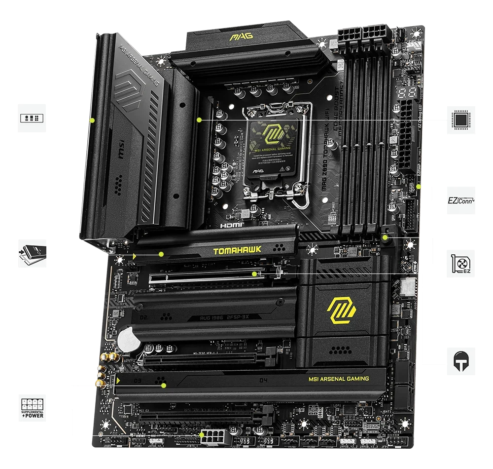
| Tomahawk position | Connection and protocol | Supported lengths |
|---|---|---|
| M2_1 | CPU Gen5 x4, PCIe | 2260, 2280 |
| M2_2 | CPU Gen4 x4, PCIe | 2260, 2280, 22110 |
| M2_3 | Chipset Gen4 x4, PCIe | 2242, 2260, 2280 |
| M2_4 | Chipset Gen4 x4, PCIe; also SATA | 2242, 2260, 2280 |
For four retained drives and a card intended for a Gen4 x4 link, this is a relevant starting layout. The next question is which lower connector remains accessible beneath your graphics card. Choosing the lower slot on a specification sheet cannot remove a cooler that physically covers it.
Five onboard drives are a different requirement: Tomahawk has no fifth onboard M.2 position.
An expansion adapter would become another device in your slot plan. If the GPU covers one lower connector and the retained card occupies the other, there is no unallocated lower connector to assume for that adapter. Draw the complete arrangement before treating an adapter as an inexpensive substitute for a fifth onboard socket. Its device count and any bifurcation requirement would also need to match the chosen slot; an adapter's advertised capacity alone is insufficient.
Preserve SATA Drives and Check ACE’s Shared 22110 Space
A SATA M.2 drive belongs in ACE or Carbon's M2_5, or Tomahawk's M2_4. The other listed M.2 positions are PCIe positions; similar-looking modules do not make the protocols interchangeable.
For example, an inventory of four 2280 PCIe drives and one 2280 SATA drive has a straightforward five-position assignment on ACE or Carbon: reserve M2_5 for SATA, then allocate the PCIe drives across M2_1 through M2_4. That solves the storage assignment; apply the expansion-card conditions separately. The same inventory exceeds Tomahawk's onboard socket count.
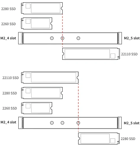
ACE's M2_4 and M2_5 cannot both hold 22110 drives. A 22110 in M2_5 leaves M2_4 for 2260 or 2280; a 2280 in M2_5 permits M2_4's full length list. The drawings show the shared space.
If your retained set includes two 22110 modules, mark that conflict explicitly. Do not assign one to each of those ACE positions merely because both table rows contain “22110.” Nor should a 22110 drive be pencilled into a shorter-only socket to make the drive count work. The allocation has to preserve the real modules you own.
Check the Covered Positions, Cooler Envelopes and Front-port Requirement
ACE's native map places M2_5 above M2_4. Locate drives by the printed labels.
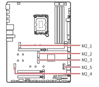
ACE's manual limits additional SSD-heatsink width to 24mm at M2_1 and 22mm at the other positions. Carbon instead shows 25mm at M2_1 and 22mm elsewhere. These width diagrams also tell you to consider the installed expansion card's height relationship.
A width check does not settle whether a tall SSD cooler clears your GPU or second card. Include the actual cooler profile, card backplate, occupied expansion positions and access needed to fasten each drive. Keep an existing heatsink only where that complete arrangement permits it; buying more cooling hardware before checking the space can create another obstruction.
If front USB-C charging is part of the purchase, ACE advertises 60W for its front 20Gbps connection with the specified PSU connection to PD_PWR1; Carbon and Tomahawk list 27W. A PD_PWR1 connector name alone does not establish the same charging capability.
Treat that as an additional requirement only if your case front connection and intended use call for it. It does not repair an unsuitable expansion-card allocation, and the charging figure should not become the reason to replace otherwise suitable storage.
Choose from the Inventory You Will Actually Keep
For an x8 second card and five onboard drives, begin with ACE's documented x8/x8 arrangement and chipset-routed M2_4, then check every SSD and the physical clearances. Carbon needs the concurrent CPU-slot answer before you rely on it for that particular requirement.
For a suitable x4 card and four drives, map Tomahawk first if it otherwise meets your needs. If five onboard drives are essential, compare the complete ACE and Carbon allocations instead of assuming a spare adapter slot. If a second CPU Gen5 SSD is essential, ACE makes the x4 second-card consequence explicit.
The useful shopping result is a board with a fully assigned retained-parts plan. Keep the GPU mode, second-card requirement, each SSD position, any length conflict and any unresolved manufacturer answer together. That makes a conditional candidate distinguishable from a configuration you can actually commit to.