A Cooler Master MasterCase NC100 can give an existing Intel NUC 9 Extreme Compute Element room for a longer graphics card. The useful carry-over is the complete Compute Element, including its processor, cooling assembly, suitable SO-DIMMs and two onboard M.2 drives. The NC100 must supply the matching chassis infrastructure around that module: its baseboard, power supply and cables, air duct, fans and front-interface connections.
Treat this as a complete-kit purchase, particularly when comparing used listings. An attractive empty NC100 shell is not a standard Mini-ITX case waiting for your old motherboard. Missing specialised parts can prevent the migration even when the Compute Element and graphics card are individually in working order. Start with the parts that make the NC100 a usable system, then judge the proposed GPU against the space and power arrangement that remains.
Buy the Complete Case Platform
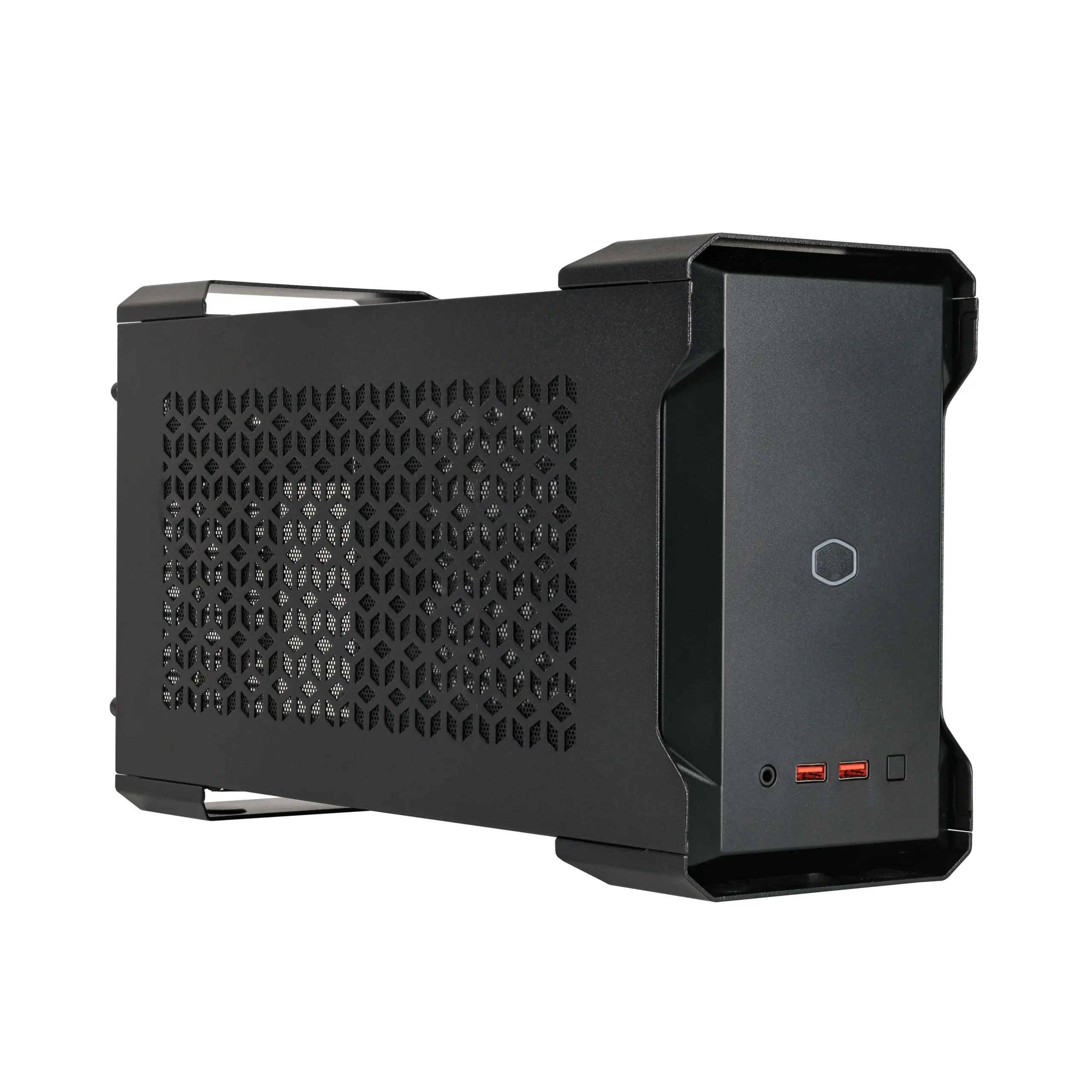
Cooler Master specifies support for Intel NUC Compute Element H, version D and above, and identifies the NUC 9 Extreme Compute Element as the intended platform. The black and white NC100 versions belong to this same case family; they are not separate motherboard standards. Confirm the exact Compute Element you own against that support description before buying the enclosure. The shared “Compute Element” name does not establish compatibility with every later module generation.
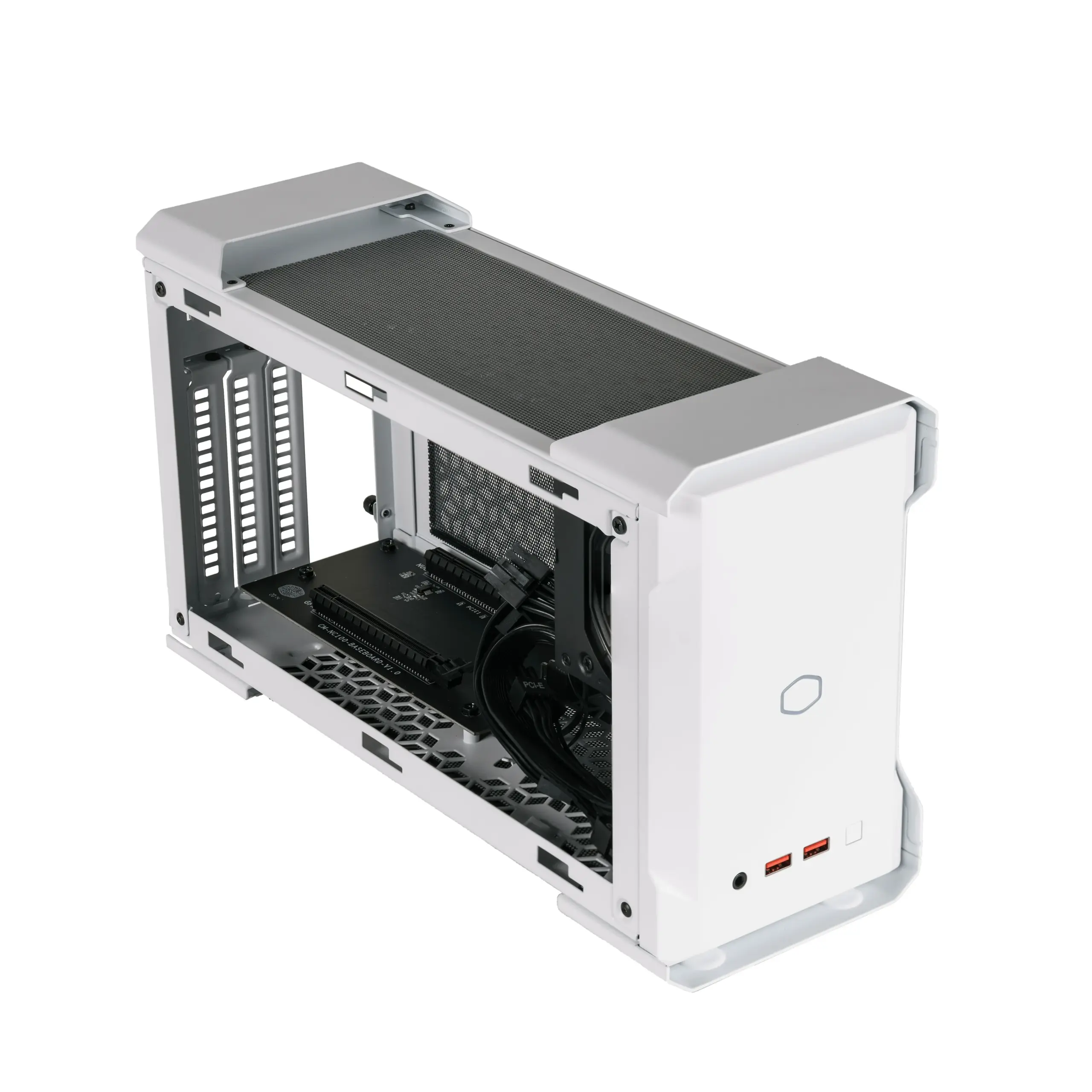
The physical difference is visible in the open chassis: a baseboard at the floor accepts the Compute Element as a card, with the graphics card alongside it. The NC100 is not an interchangeable home for a conventional Mini-ITX motherboard and socketed desktop CPU. Keep the matching NC100 baseboard in the purchase inventory, including its mounting and rear retention hardware.
The published enclosure dimensions are 370 × 128 × 214mm. Its quoted 7.9-litre volume excludes protrusions, so use the external dimensions when deciding whether the finished case fits your desk or shelf. Leave room for rear connectors and ventilation as well as the metal enclosure. A smaller volume figure does not remove the need for cable access.
Before agreeing to a used purchase, ask for internal photographs with both side panels removed and a list of included accessories. Establish that the seller is offering the baseboard and power supply as well as the outer panels. Then identify the air duct, top fans, front-interface leads, GPU retention pieces and appropriate power cables. A photo showing the shell from the outside cannot answer those questions.
Keep the Compute Element and Identify Its Own Drives
The NUC 9 Extreme Compute Element carries the soldered processor and its cooling assembly. Moving that complete module preserves the CPU arrangement; it is not an opportunity to transfer the processor into a different desktop motherboard. Intel's documented Extreme configurations include the i9, i7 and i5 versions associated with NUC9i9QNX, NUC9i7QNX and NUC9i5QNX kits. Check the label on the actual module rather than identifying it solely from the enclosure it came out of.
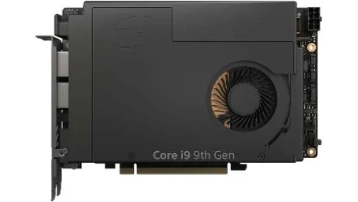
The memory belongs to the module too. Intel specifies two 260-pin DDR4 SO-DIMM sockets, 1.2V memory and up to 64GB total capacity. Retain a working, supported pair with the module if it already meets your capacity needs. This migration does not convert the sockets to DDR5 or accept long desktop DIMMs. If additional memory is needed, verify it against the original module's requirements rather than selecting it from an NC100 case listing.
Make a physical drive inventory before dismantling the old system. There are two M.2 storage positions on the Compute Element itself. Both accept 2242 or 2280 modules, and the outer position also accommodates 22110. Intel specifies support for NVMe over PCIe Gen3 ×4 and SATA M.2 storage in the module's storage arrangement; check each retained drive and its actual position.
The distinction matters because the original Intel NUC 9 kit also has an M.2 NVMe position on its chassis baseboard. That third drive is not located on the removable Compute Element. Moving the module therefore does not automatically move all the storage installed in an original three-drive system. Similarly, the original kit's additional PCIe ×4 position and front SD reader are not features to assume on the NC100.
| Existing item | Does moving the Compute Element carry it? | What to establish first |
|---|---|---|
| Soldered CPU and module cooling assembly | Yes, as part of the complete module | Correct module identity, intact cover and cooling parts |
| Two module-mounted SO-DIMMs | Yes, if retained in the module | Supported DDR4 type and desired capacity |
| Two module-mounted M.2 drives | Yes, in their existing supported positions | Drive interface, length, retaining hardware and data location |
| Original Intel baseboard's third M.2 drive | No automatic carry-over | A separate supported destination if that drive is needed |
| Original chassis front SD reader | No automatic carry-over | Whether you still need that function in the new setup |
Keep the module's own cover, fan and small fixings with it. Back up needed data before the hardware move, and account for files on any drive that will remain behind. A system that starts from one retained SSD can still be missing data stored on the old baseboard's separate drive.
Use the Case Power Supply and Its Matching Leads
The NC100 manual identifies the included PSU as the Cooler Master V650 SFX Gold. The case specifications limit the power-supply length to 100mm. This differs from the original Intel NUC 9 kit's Flex-ATX 500W arrangement, so do not put the old kit's PSU into the “automatically reusable” column.
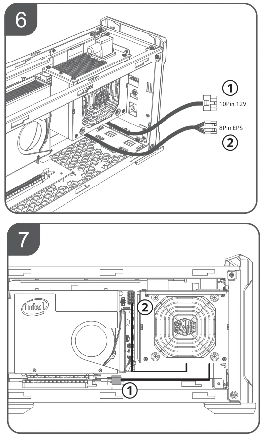
Two separate power connections serve the NC100 platform. The manual labels the 10-pin 12V lead for the baseboard and the eight-pin EPS connection for the Compute Element. Its numbered drawings show where those leads go. The module's eight-pin connection does not eliminate the baseboard's power requirement, and the baseboard connection is not a substitute for powering the module.
Ask the seller to show the matching ten-pin lead clearly. It is one of the important differences between a complete NC100 kit and a collection of familiar-looking SFX parts. A generic replacement PSU with enough wattage is not a complete solution unless the required NC100 connections and supported cables are also established. Do not mix modular cables from the old NUC, another ATX PSU or an unidentified spare-parts box.
The documented supplied cable set also includes two 6+2-pin PCIe GPU power connections and two SATA power connections. Keep the original matched set together, even if the GPU you intend to retain does not need both PCIe connections. Include the regional mains lead and confirm the condition of the supply and its connectors when inspecting a used kit.
This is a wiring inventory, not a request to recreate missing cables. If a seller cannot identify the correct ten-pin cable or the PSU-side connections, resolve that with Cooler Master or a qualified supplier before buying. Disconnect mains power before internal work; the original Intel guidance also warns against opening or servicing the system with the AC cable attached.
Keep the Air Duct, Fans and Closing Panels
The NC100 air duct is a shaped part of the Compute Element's intake arrangement. Cooler Master's assembly drawings show it fitted around the module, and its product sheet describes the dedicated duct supplying fresh air to the Compute Element. Do not mistake the loose duct for packaging or an optional decorative insert when a seller lays out the accessories.
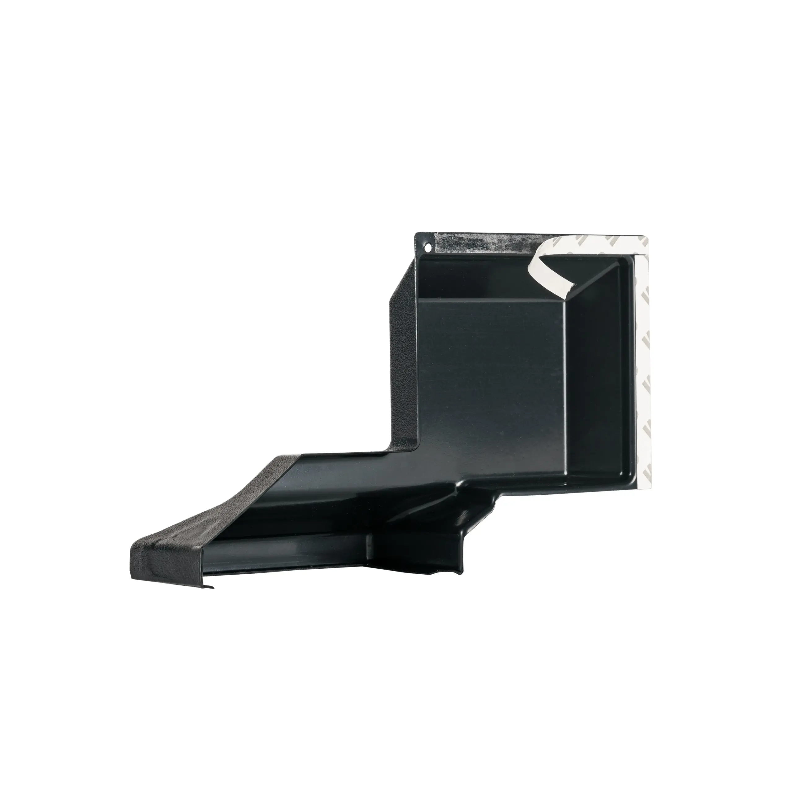
The real duct photograph helps identify the piece: its stepped profile and broad opening are specific to the enclosure layout. Retain its matching attachment arrangement and check its condition. A missing duct should be a named gap in the offer, rather than something silently replaced by the assumption that a more open enclosure will cool well enough.
The case also includes two slim 92mm PWM top fans, with a splitter shown in the manual. Check for both fans and that connection, together with the top filter and the panels needed to complete the enclosure. A missing splitter or an incorrect replacement fan can change the required cable and clearance arrangement even when the fan diameter sounds right.
Judge the assembled arrangement with the panels and filter in their intended positions. An open-chassis product photograph is useful for seeing parts, but it does not prove a proposed cable route or tall component will clear the closed case. These are completeness and fit checks; the manufacturer's cooling description is not a measured temperature or noise result for your retained module and new GPU.
Screen the Complete Graphics Card, Including Its Plugs
The NC100 offers substantially more card length than the original Intel kit, but length is only one of three dimensions. Cooler Master's product sheet lists 320 × 51 × 130mm for the GPU envelope while recommending 112mm card height for maximum compatibility. Its assembly manual gives 320mm maximum length, 112mm maximum height and 2.5-slot maximum depth.
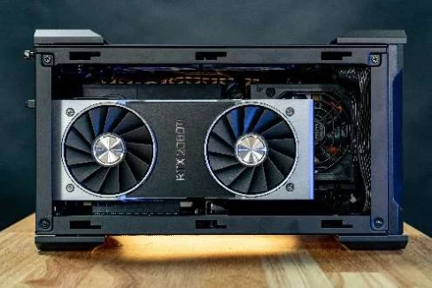
For an initial purchase screen, use 320mm length, 51mm thickness and 112mm height together. Treat a card between 112 and 130mm tall as needing explicit confirmation for that exact card and cable arrangement, rather than approving it from the larger headline number. The figures describe different qualifications; they should not be combined into an unconditional promise that every 320 × 51 × 130mm card fits.
The installation photograph shows a manufacturer's example of a long GPU inside the NC100. It illustrates where the card sits relative to the PSU and chassis, not approval of an unidentified replacement card. Obtain the full dimensions of your exact GPU variant, including its cooler, backplate and projecting parts, and establish the measurement convention used for its height.
Inspect the power-connector location and the room needed by the attached plugs and cables. A card body that clears the enclosure can still leave an unusable cable exit. Check the side panel, duct, rear bracket and retaining hardware in the completed arrangement. A “2.5-slot” description alone does not replace the separate 51mm thickness check.
Power is another independent decision. The supplied 6+2-pin leads must match the GPU's required connection arrangement, and the entire system must suit the selected PSU and card requirements. Do not read the V650 model's wattage as the GPU's personal power allowance. Equally, the original Intel kit's 225W add-in-card limit describes that original kit; it is not a newly established NC100 GPU rating. Confirm the proposed combination without borrowing either shortcut.
If the card needs an unverified power connector arrangement, or the seller cannot settle the height and plugged-in clearance, keep that GPU choice unresolved. The enclosure migration should enable a suitable longer card, not force the purchase of a particular card before the full fit has been checked.
Reconnect the Front Interface and Retain the Module’s Rear Ports
The NC100 front panel provides two USB 3.1 Gen2 Type-A ports and a combined 3.5mm headset jack. Those sockets depend on their internal connections; they do not become functional just because the Compute Element has been seated in the baseboard.
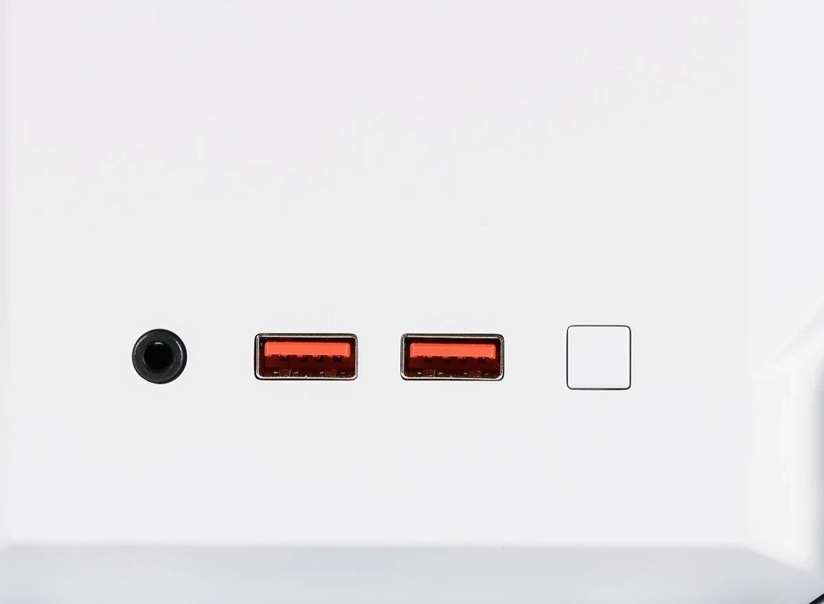
The manual separates the Front Panel IO extension, USB 3.1 cable and audio cable. Ask for all three corresponding connections in a used-kit photograph and follow the NC100 drawing when reconnecting them. In particular, identify the included front-panel extension rather than assuming a conventional ATX motherboard header cable will replace it. The front buttons and sockets should be part of the same completeness check as the power wiring.
The optional ARGB arrangement is worth identifying too. The included controller can take the reset-switch connection so that the case button selects lighting presets. If that arrangement is used, do not also describe the button as an ordinary reset control. Keep the lighting controller and leads with a complete kit, but do not make lighting a reason to buy unrelated accessories for the migration.
Rear connections such as HDMI, LAN and the two Thunderbolt 3 ports belong to the retained module's platform. The case change does not turn them into newer-generation interfaces. Intel also notes that the two Thunderbolt 3 connections share their available bandwidth, so the pair is not two independent full-bandwidth paths simply because both sockets remain accessible. Check the rear opening and cable access for the installed module.
Complete the Antenna Path Before Relying on Wireless
The Compute Element's soldered wireless hardware is only part of the wireless system. Intel describes appropriate antennas as necessary for Wi-Fi and Bluetooth operation and identifies the module's MMCX-style antenna connections. The original kit uses its own internal antenna arrangement, so inspect which leads and fittings will actually remain available when you remove the module.
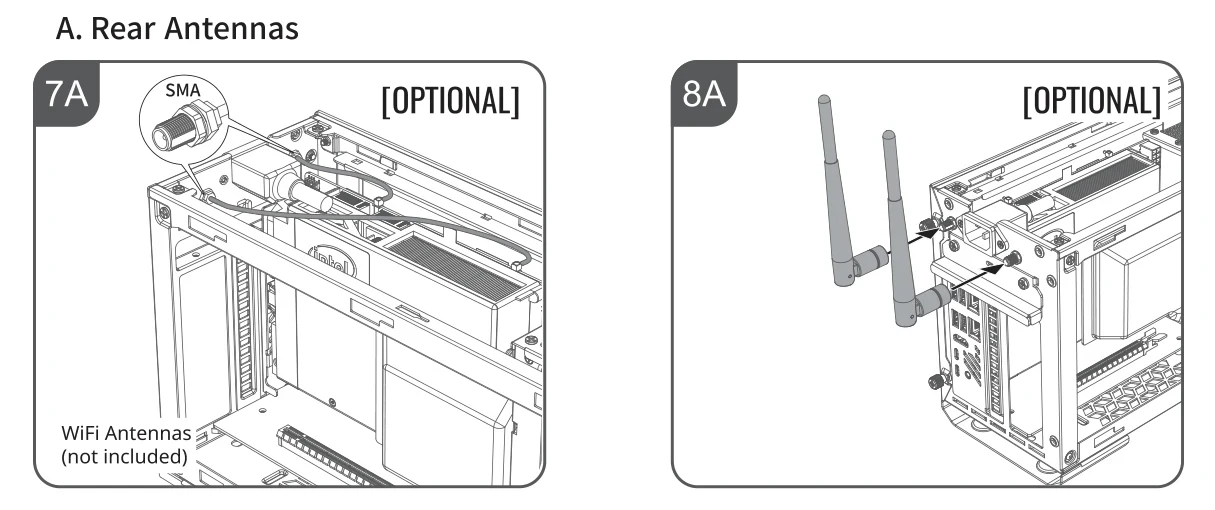
The NC100 manual shows optional rear and front antenna arrangements. Its rear-antenna drawing explicitly says that the Wi-Fi antennas are not included. Neither a soldered AX200 radio nor a photograph of an NC100 with two external antennas establishes that a used case listing supplies the complete antenna kit.
Check the whole chain: connections at the module, suitable leads, chassis fittings and antennas. Establish that the connectors at both ends match the intended NC100 arrangement. Keep the original module's appropriate antenna leads where useful, but do not force an old connector onto a superficially similar fitting or assume the original chassis antenna mounting will transplant intact.
Choose one documented placement that suits the actual parts. The front and rear drawings are alternatives, not a promise that every fitting is included twice. Also keep the manual's 130mm antenna-clearance illustration separate from GPU selection: that antenna drawing does not override the manual's 112mm GPU-height specification.
Compare the Finished Kit with What You Already Own
The most useful final comparison is between a complete NC100 offer and the specific retained module, drives and GPU. Keep the small proprietary pieces beside the major components in the inventory.
| Keep from the existing system | The NC100 offer must supply or resolve |
|---|---|
| Correct NUC 9 Extreme Compute Element, its CPU cooler, cover and fixings | Matching NC100 baseboard, module retention and complete enclosure |
| Supported DDR4 SO-DIMMs and two suitable module-mounted M.2 drives | A separate plan for any old baseboard-mounted third drive |
| A GPU only after its full dimensions and power arrangement qualify | Bracket fixings, cable exits and the supplied matched GPU leads |
| Useful module-side antenna parts after identifying their connectors | Complete compatible antenna path and chosen chassis mounting |
| Existing external peripherals and suitable rear-port cables | Front IO extension, USB/audio leads, V650 SFX power set, duct, fans, splitter and filter |
For example, a working NUC 9 Extreme module with two onboard SSDs and enough DDR4 can remain the centre of the build while the NC100 provides room for a longer GPU. That is a sensible paper plan once the exact card, power connections and complete case kit qualify. If the old machine also contains a third SSD underneath the module on the Intel baseboard, that drive needs a separate decision before the old chassis is retired.
Do not use this case change as evidence of a CPU upgrade, newer operating-system qualification or guaranteed performance improvement. It changes the enclosure and its supporting infrastructure around the retained platform. Buy when the complete inventory and exact GPU conditions fit together; leave an incomplete shell or an unexplained specialised cable out of the order until the gap is resolved.