You can keep older NZXT RGB fans when adding an F360U or F420U Ultra single-frame fan. The choice is whether your motherboard can safely power and control the new frame while the old lighting stays on its existing controller, or whether a new Control Hub can accommodate the complete collection. Replacing every working fan is unnecessary; treating every NZXT connector as interchangeable is where the plan breaks down.
For motherboard wiring, the standalone Ultra frame includes an adapter. It still needs adequate motor power and a suitable lighting connection. For a Control Hub, budget the channels, LEDs, PSU connection and internal USB connection before buying. A free socket alone does not establish compatibility.
Identify the Fans You Are Keeping
Start with the complete model name, rather than “NZXT RGB.” Older individual F120/F140 RGB Core and RGB Duo fans need an NZXT controller for lighting; connecting their motor cables to motherboard fan headers does not transfer their lighting to motherboard ARGB control. Current F120 RGB/F140 RGB and Ultra F120U/F140U models have different connection options. The similar names do not make their cables equivalent.
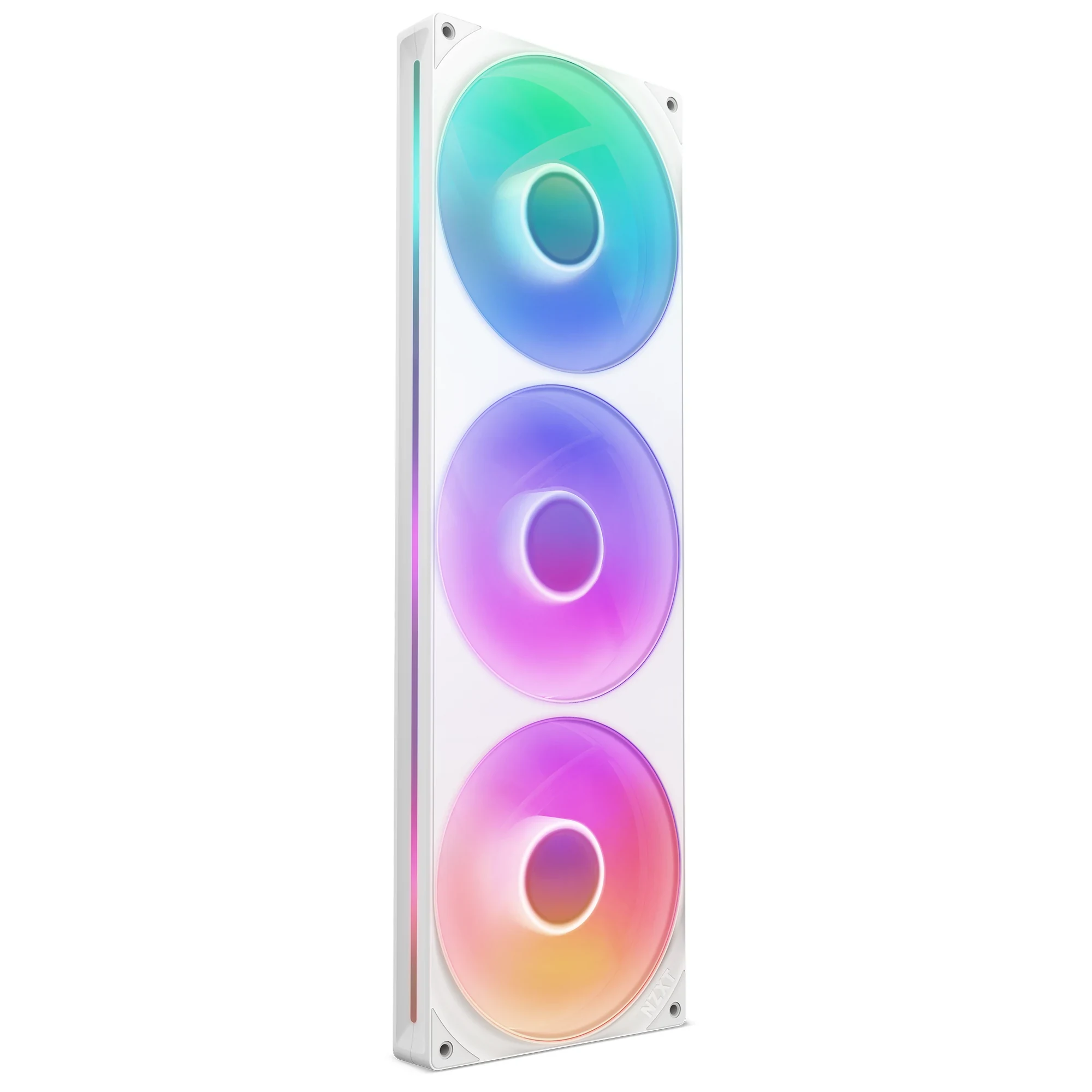
Single-frame RGB Core fans are another category. An F420 RGB Core combines three fans in one frame and can use its supplied adapter for motherboard connection. That does not mean an older individual F140 RGB Core gains the same option. Likewise, check the manual and original interconnects for an Aer RGB installation before moving it. Older Aer fans may have a dedicated connection arrangement.
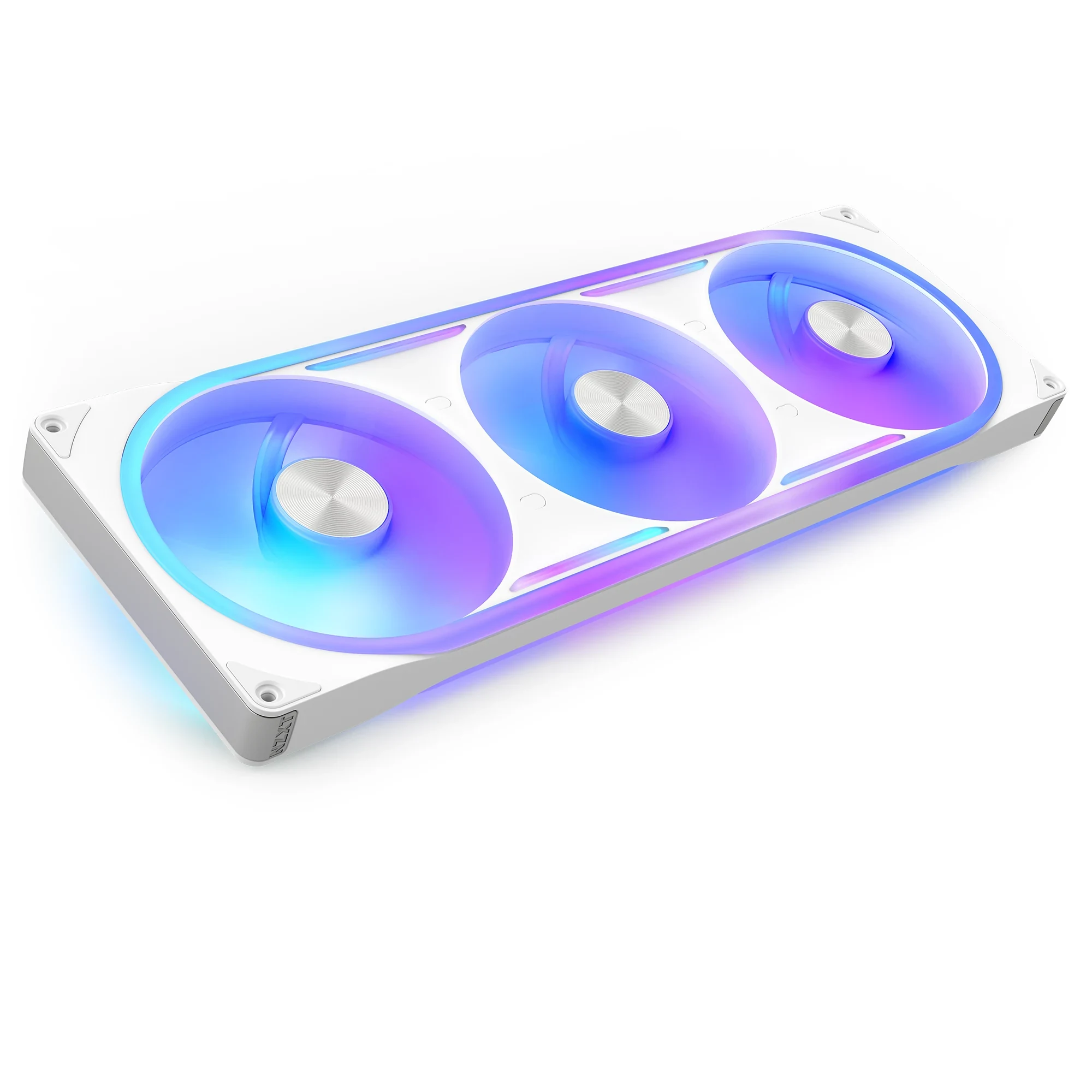
The F420 RGB Core shown here also differs from the F420U Ultra in the title. Both occupy a 420 × 140 × 25 mm envelope, but the Core specification lists eight LEDs per fan, or 24 across the three-fan frame; the Ultra frame has 96. Their electrical demands differ too. Retain the exact model in your parts list throughout the decision.
Follow the Ultra Adapter Before Choosing a Controller
An F360U or F420U uses one NZXT 8-pin cable for its integrated fans and lighting. On a compatible NZXT 8-pin controller port, that cable connects directly. Without such a port, the included adapter separates the connections into a 4-pin PWM fan lead and lighting plugs offering either NZXT RGB or motherboard 5V ARGB.
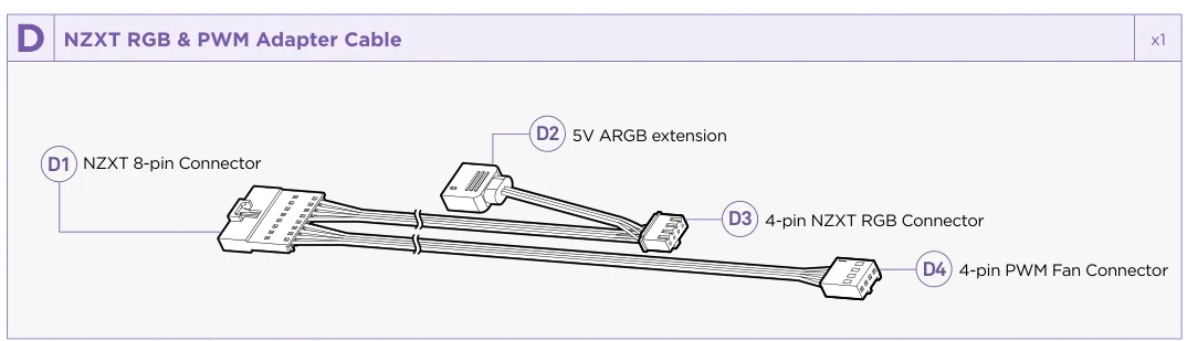
The drawing shows why the adapter is useful: the motor and lighting can reach different destinations. For example, the new frame can run from a suitable motherboard fan header and 5V ARGB header while your older proprietary RGB fans remain on their existing controller. This preserves the old lighting hardware without making it responsible for the new frame's motor load.
Do not replace a missing original adapter with an unidentified “RGB splitter.” A splitter adds connections to a known system; it does not establish the correct pinout or convert an older proprietary lighting device into a standard ARGB device. Obtain the connection hardware specified for the exact fan before treating that route as a complete purchase.
Choose One Lighting Destination
On the Ultra adapter, use the 4-pin NZXT RGB connection or the 3-pin 5V ARGB connection. Leave the unused lighting plug disconnected. Do not connect both, and do not put the NZXT lighting plug into a motherboard's 12V RGB header. NZXT warns that incorrect lighting connections can damage the equipment. The physical branch drawing is an alternative-path drawing, not an instruction to fill every plug.
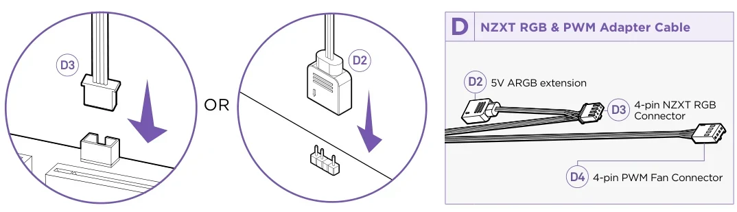
Motherboard connection normally puts lighting under the motherboard's RGB software and fan speed under its fan-control facilities. NZXT describes direct 5V ARGB as basic Ultra lighting; full multi-zone control in CAM requires a Control Hub or a compatible NZXT motherboard. Decide whether those effects matter before paying for a controller. Matching a static color across two systems is a different goal from controlling every device through one interface.
Check the board's actual ARGB-header current and supported LED count as well as its voltage. “5V ARGB” identifies the interface, not an unlimited supply. An available fan header does not establish that the separate lighting header can run a 96-LED frame.
Calculate Motor Power Separately from Lighting
One frame has one cable, but it contains three fans. Use the specification for the exact complete-frame model; do not treat the frame as one low-current individual fan, and do not multiply an already complete-frame rating by three. The manufacturer specifications give the following separate budgets.
| Complete frame | Motor at 12V | Lighting at 5V | LEDs |
|---|---|---|---|
| F360U Ultra | 0.9A / 10.8W | 1.45A / 7.25W | 96 |
| F420U Ultra | 1.03A / 12.36W | 1.4A / 7W | 96 |
| F420 RGB Core | 0.95A / 11.4W | 0.81A / 4.05W | 24 |
A motherboard fan header rated at 1A provides a 12W motor budget at 12V. An F420U exceeds that rating by itself. An F360U is below it, but leaves only 0.1A before reaching the stated limit, so do not add another fan on a splitter without recalculating. Use the actual board manual: some headers have different ratings, and connector shape does not identify them.
The F420U's listed 19.36W total input includes both motor and lighting. It is not a 19.36W load on the motor header. Conversely, having an adequate 12V fan header does not cover the separate 5V lighting demand. Keep the two calculations separate, including any other devices sharing either channel.
An older RGB & Fan Controller's 10W fan-channel limit is also below the F360U's 10.8W and F420U's 12.36W motor demand. Do not select that controller as their motor-power source. Keeping it for already supported old fans is a separate decision. Also avoid copying the guide's 8.16W figure for the differently named F420 RGB onto this F420 RGB Core: the Core specification above lists 0.95A at 12V.
What the New Control Hub Provides
The Control Hub considered here is model AC-CRFR1-B1. Its five fan channels consist of four NZXT 8-pin outputs plus one standalone 4-pin PWM output. For lighting, it has four 8-pin channels plus one legacy NZXT RGB channel. “Five channels” therefore does not mean five direct 8-pin frame connections.
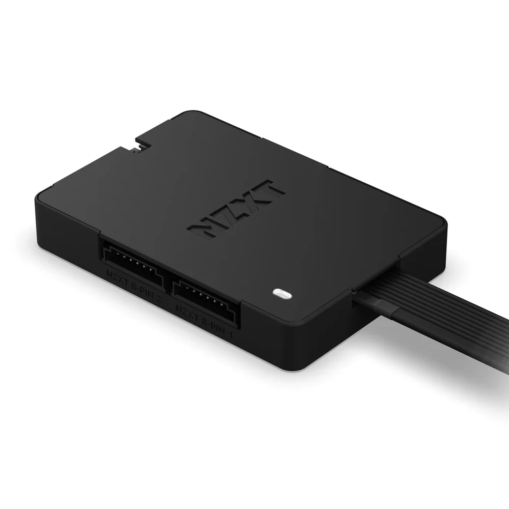
Each fan channel is rated for 12V, 1.1A, or 13.2W. Each lighting channel is rated for 5V, 3.1A, or 15.5W. One F360U or F420U frame fits those respective electrical ratings on a suitable 8-pin channel. These are per-channel budgets: unused capacity elsewhere on the controller does not enlarge an overloaded channel.
The LED limits matter independently. An 8-pin channel supports up to 96 LEDs, while the legacy NZXT RGB channel supports up to 40 LEDs and up to five NZXT devices. Both limits apply to that legacy channel. One 96-LED Ultra frame uses the entire LED allowance of its 8-pin channel; a splitter cannot make a second such frame fit that allowance. The legacy 40-LED channel is not an alternative lighting destination for the complete 96-LED Ultra frame.
The hub can be a sensible purchase when the motherboard's motor budget is inadequate or when full Ultra lighting control in CAM is important. It is less compelling if the board already meets both budgets and you are comfortable retaining a separate old lighting controller.
Map the Old Fans Onto Actual Channels
Draw the motor and lighting connections for each retained fan separately. Older four-pin PWM motors may use the appropriate fan connection or supplied splitter, while legacy NZXT RGB lighting goes through the corresponding NZXT RGB connection hardware. A legacy RGB plug is not a direct substitute for the new frame's combined 8-pin connector.
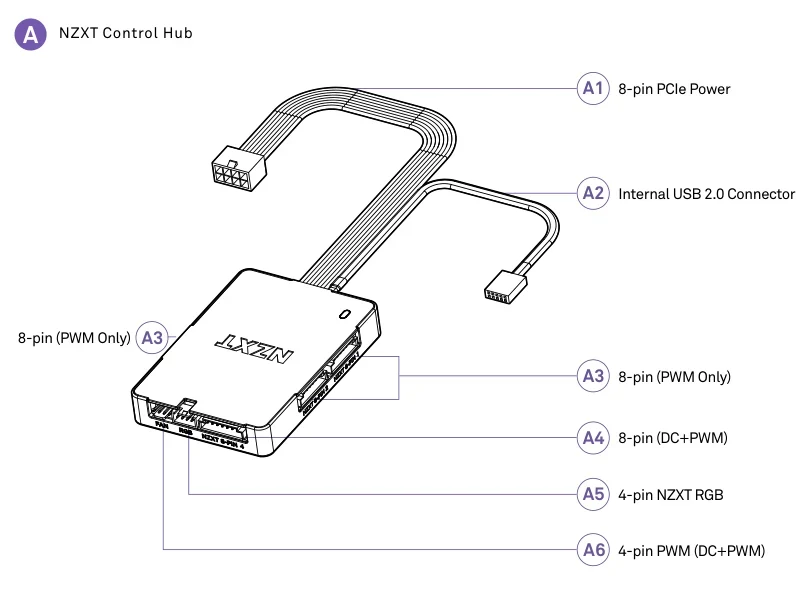
For a retained three-pin motor, select an output that supports DC voltage control. The Control Hub manual specifically directs case-version RGB fans needing DC speed control to channel 4; the standalone 4-pin fan output also supports DC and PWM. Do not assume a PWM-only channel will provide the intended speed control for a three-pin motor. Read the markings on the actual controller while planning the route.
NZXT's Control Hub manual also prohibits mixing different lighting accessory types within one channel, naming F-series RGB fans, Aer RGB fans and LED strips as examples. An old Aer chain that includes other accessory types should not simply be transplanted onto one new hub channel because its total is below 40 LEDs. Retain its supported old arrangement or establish separate compatible routes before retiring the old controller.
Use no more than one 1-to-3 splitter per channel, as the manual specifies. Add the connected motor currents, lighting currents and LED counts for each resulting branch. A splitter does not provide independent speed channels: fans sharing a cooling channel share its speed setting. If the complete collection cannot fit within the electrical, LED and accessory-type limits, a second retained controller may be more practical than replacing working fans.
Reserve Both PSU Power and Internal USB
The new Control Hub needs an 8-pin PCIe PSU connection and an internal USB 2.0 motherboard connection. Use the PSU's appropriate 6+2-pin PCIe/VGA lead, not its 4+4-pin CPU/EPS lead. NZXT explicitly warns against that substitution. Turn the PC off before making these connections. The hub's combined 8-pin fan ports are also a different interface from its 8-pin PSU power input.
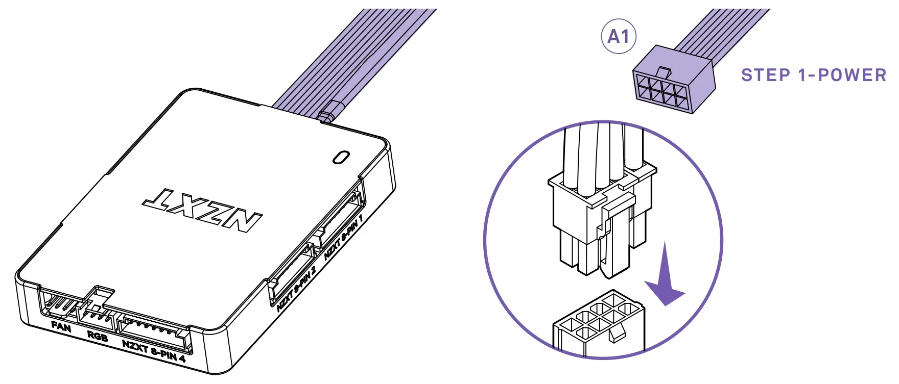
Older RGB & Fan Controllers and the Control Hub Lite use SATA power with internal USB, so an existing SATA connection does not complete the new hub's power requirement. Count the new power lead in the upgrade rather than assuming you can reconnect everything exactly as before.
If you retain an old controller alongside the new hub, reserve the required power and USB connections for both. Check what is already using the board's internal USB headers, including any cooler. A plan with no available USB connection is incomplete for normal CAM control. NZXT recommends an active internal USB hub when expansion is necessary; do not assume a simple passive PCB splitter will provide equivalent operation.
This distinction also helps with setup: check both power and USB if CAM does not detect the controller. The Control Hub manual describes different indicator behavior for missing USB and missing PCIe power, so an illuminated controller or spinning fans alone should not be treated as proof that the USB control path is connected.
Check Frame Fit and Controller Placement Together
The F360U measures 360 × 120 × 25 mm; the F420U measures 420 × 140 × 25 mm. Choose the frame that matches the intended mounting location. Retaining three individual fans elsewhere does not establish that a continuous Ultra frame can occupy their former position. Check the actual case or radiator mounting arrangement and surrounding obstructions. Both Ultra frames list a 600 mm cable, which must reach the selected connection route.
The Ultra manual lists an adapter cable, four case-mounting screws and four radiator screws. Keep those sets with the frame and use the fastening arrangement appropriate to the chosen mount; the two screw sets are not eight interchangeable case screws. A used or open-box purchase with missing adapter or mounting hardware needs that gap resolved before installation.
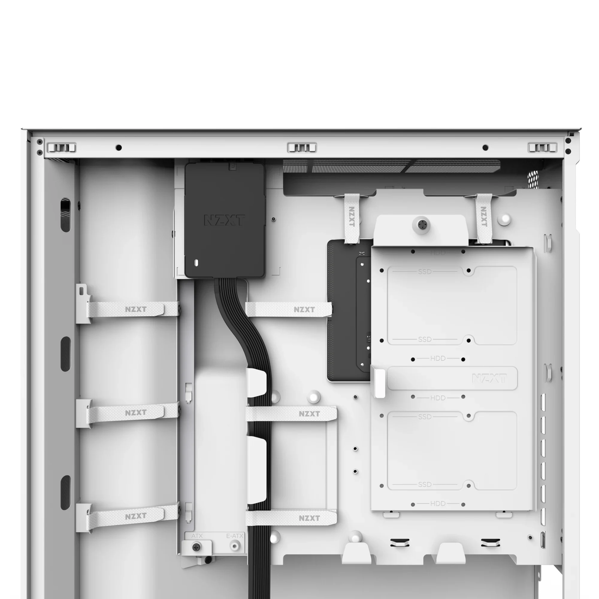
The Control Hub measures 100 × 70 × 16 mm. It can mount magnetically, with the supplied Dual Lock, or using its two screw holes on a suitable 2.5-inch tray with M3 screws from the case accessories. The manual calls for checking connector clearance. The rear-case photograph shows why controller location belongs in the purchase plan: the enclosure may fit while the exiting cables still need routing space beside drive trays and straps.
Choose the location before committing to adhesive mounting. Leave access to the old controller if it remains in use, and check that neither controller's leads are pulled tight when the side panel closes. Cable length on a specification sheet does not prove a particular route will fit.
Choose the Smallest Complete Upgrade
For example, suppose you are keeping older individual F-series RGB fans on a working controller and adding one F420U. A spare motherboard fan header rated at 1A is insufficient for the new frame. Keeping the old controller does not solve that motor deficit, and moving the Ultra onto an old 10W channel does not solve it either. A suitable higher-rated motherboard header or the new Control Hub is needed for the frame's motor power; its lighting needs its own compatible, adequately rated destination.
With an F360U instead, an otherwise unused 1A header meets the listed 0.9A motor demand, but the motherboard lighting header must still support the frame's 5V current and LED requirements. If both checks pass and basic lighting is sufficient, retaining the old controller and using the included adapter can avoid buying a new hub.
| Route | Keep | Add or reserve | Leave unresolved until checked |
|---|---|---|---|
| Old controller plus motherboard Ultra connection | Supported old fans, original lighting wiring and controller | New frame, included adapter, adequate fan and 5V ARGB headers | Exact board header ratings, LED support and frame fit |
| Migrate a compatible collection to one Control Hub | Existing fans and their correct connection hardware | Hub, PCIe power, internal USB, mounting space and a channel plan | Every legacy branch's current, LEDs and accessory type |
| Keep old lighting controller and add a hub for Ultra | Existing supported lighting arrangement | Hub connections and a separate suitable 8-pin channel for Ultra | USB availability for both controllers and cable routing |
Choose motherboard connection when its verified budgets and basic control meet your needs. Choose the Control Hub when its channel arrangement and CAM features solve a real limitation. Keep the old controller when it still serves compatible retained devices that do not sensibly fit the new channel plan. The finished shopping list should account for the frame, adapter, power, USB, mounting hardware and every retained lighting branch—not merely the fan model you want to add.