Both the ASRock A520M-ITX/ac and B550 Phantom Gaming-ITX/ax list four SATA connectors and two DDR4 memory sockets. Either belongs on the shortlist for shrinking an existing AM4 machine while retaining four cabled SATA drives. The deciding differences are what else must move: a SATA-interface M.2 SSD, one or two NVMe SSDs, a graphics card and the case's front USB-C lead.
The A520 board offers one 2280 M.2 position supporting SATA or PCIe Gen3 x4 storage. The B550 board offers two 2280 positions: a PCIe-only front slot whose generation depends on the CPU, and a rear slot supporting SATA or PCIe Gen3 x4. B550 also adds an internal front-C header and faster network interfaces. Those features matter only if they solve an actual requirement in the retained-parts plan.
Start with the CPU and the Two Memory Sockets
This comparison concerns ordinary non-ECC DDR4 builds retaining Vermeer or Cezanne AM4 processors. Find your exact processor in the selected motherboard's current CPU support list and check the BIOS required. A broad AM4 or Ryzen 5000 label is insufficient purchase confirmation.
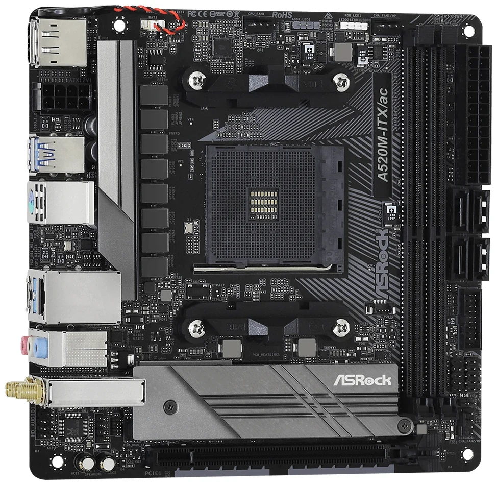
Both boards publish a 64GB maximum across two DDR4 DIMM sockets. A suitable existing two-module kit may therefore remain part of the build, after checking its supported configuration. Four modules cannot all transfer. For example, moving two sticks from a four-by-16GB kit leaves 32GB; keeping 64GB would require a supported two-module arrangement.
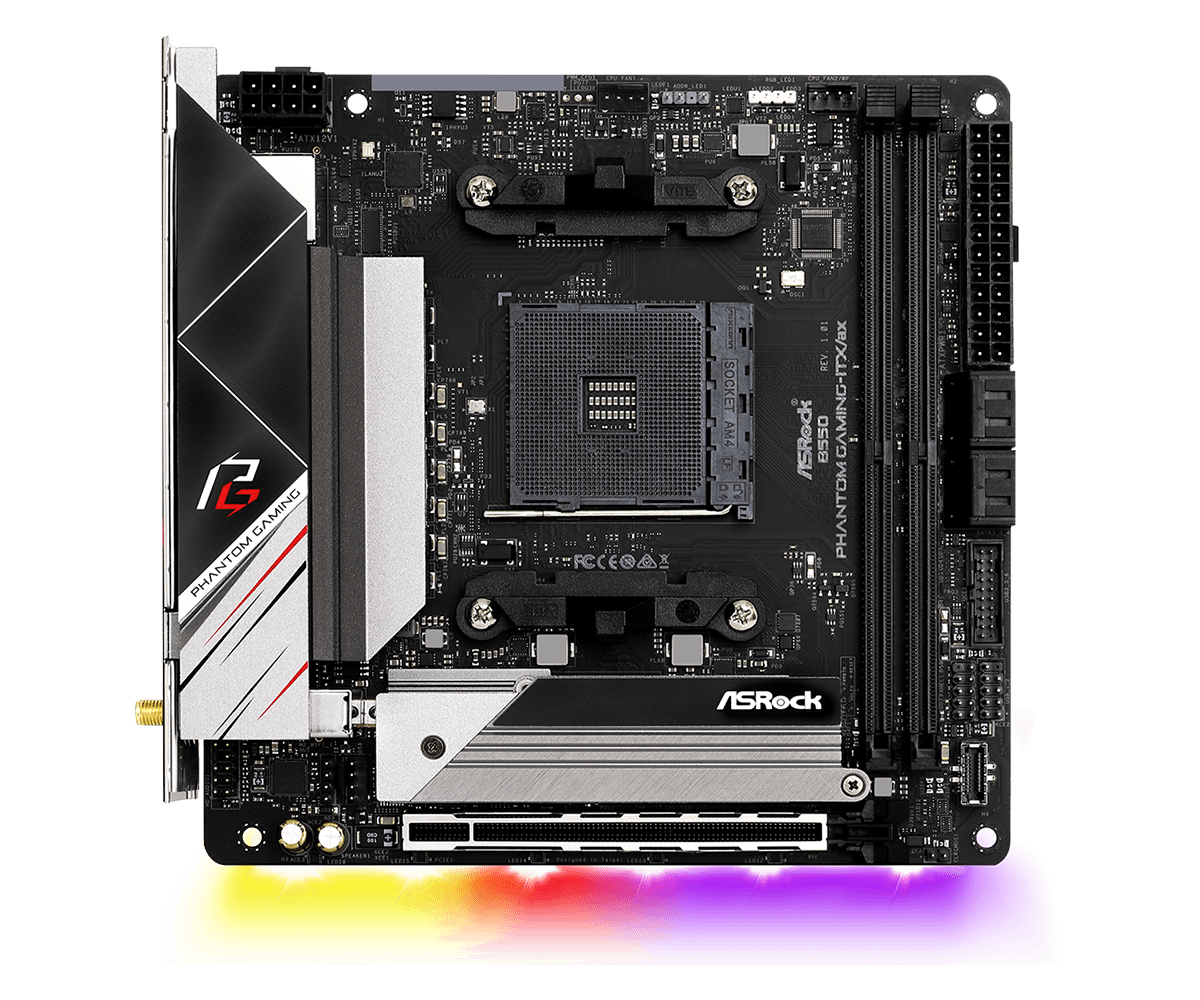
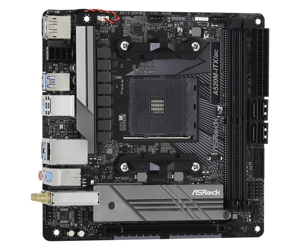
The A520 board view makes the physical limit clear: two long memory sockets occupy its right side, beside the main power connection and SATA connectors. Choosing the more feature-rich B550 board does not add two extra memory sockets. Compare supported capacity and the actual kit, rather than using memory overclocking figures as a guarantee that the old settings will work.
Also preserve a workable firmware plan before dismantling the old machine. Confirm the BIOS supplied on the replacement unit instead of assuming that a supported CPU family means the installed firmware is already suitable.
Four SATA Connectors Are Only One Part of a Four-drive Build
Each board lists four SATA 6 Gb/s connectors. The A520 close-up shows them in two stacked pairs along the right edge; its manual identifies the groups as SATA3_1_3 and SATA3_2_4. B550 likewise provides four SATA connections in two stacked groups. Count the individual sockets, not just the two visible connector housings.
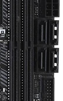
For four cabled drives, the shopping inventory must include four SATA data leads, enough suitable PSU power connections and four usable drive mounting positions in the actual case. Both manufacturers' accessory lists specify only two SATA data cables. Retaining the old leads may cover the difference; a motherboard package should not be assumed to supply all four.
Cable orientation matters when shrinking. Check where each SATA plug exits, whether the latch remains accessible and how the cables pass the case wall or drive cage. A right-angle plug is useful only when its actual direction suits the socket and surrounding parts. Do this with the chosen case and PSU layout before buying extra leads.
The board's 170 × 170mm Mini-ITX outline does not establish four-drive case capacity. For example, four 3.5-inch hard drives need different mounting provision from four 2.5-inch SSDs. Keep those physical drive identities on the list even though both use SATA data connections.
Put Each M.2 Drive in a Compatible Position
“M.2” describes neither a single electrical interface nor an unlimited set of drive lengths. For these boards, the listed storage length is 2280. Identify whether each retained SSD is SATA or PCIe/NVMe before assigning it a socket.
| Storage position | Supported 2280 interface | Relevant limit |
|---|---|---|
| A520 M2_1 | SATA or PCIe Gen3 x4 | One storage position total |
| B550 front M2_1 | PCIe Gen4 x4 with Vermeer; Gen3 x4 with Cezanne | SATA M.2 is not listed here |
| B550 rear M.2 | SATA or PCIe Gen3 x4 | Install with underside access available |
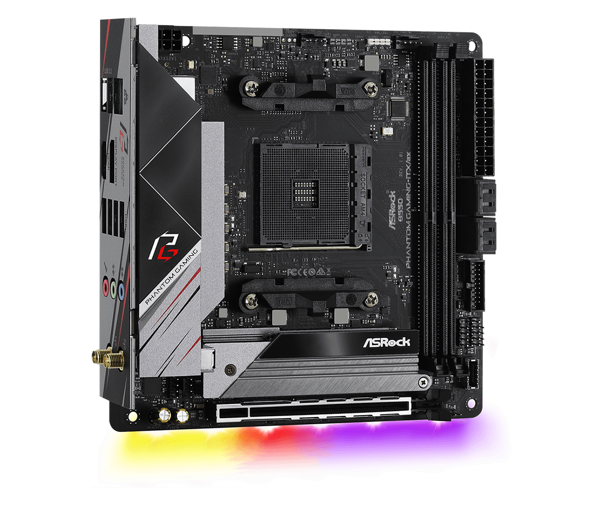
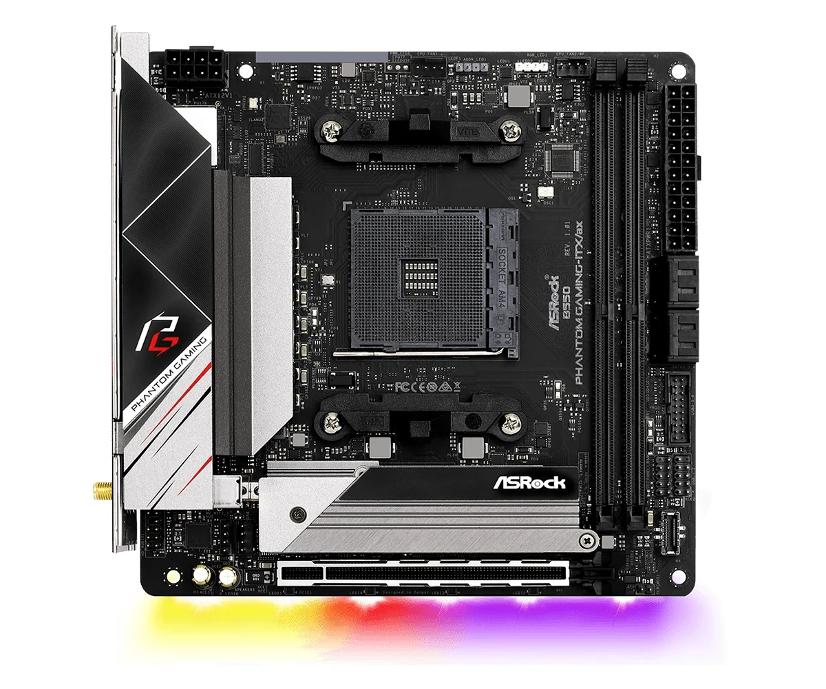
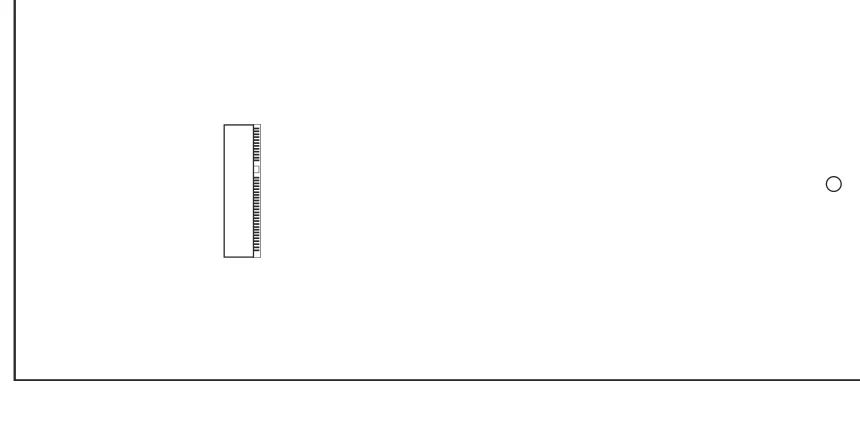
The B550 underside detail locates the second storage connector and its mounting point relative to the board edges. It is a back-side view, not a top-side location to copy onto the visible face. Plan installation and access before fitting the motherboard against the case tray; check any SSD heatsink against the actual clearance.
These assignments produce three different retained-drive plans:
- Four cabled SATA drives plus one SATA M.2 SSD: the A520 SSD occupies its only M.2 position. On B550, assign that SSD to the rear compatible position, leaving the PCIe-only front slot available for a suitable NVMe drive.
- Four cabled SATA drives plus two 2280 NVMe SSDs: B550 has the two native positions needed. A520 has only one, so the second SSD needs a change to the plan.
- Four cabled SATA drives plus two SATA M.2 SSDs: B550's two M.2 positions do not solve this natively. Only the rear position lists SATA support; the front position is PCIe-only.
For a mixed pair—one 2280 NVMe SSD and one 2280 SATA M.2 SSD—B550 assigns NVMe to the front and SATA M.2 to the rear. A520 cannot accommodate that pair in its single native M.2 position.
Use those as interface assignments, then check the actual drives, mounting parts and case access. Do not turn a spare Wi-Fi Key-E socket into a third storage position or assume an adapter will preserve every other connection. If you already need the sole long expansion slot for graphics, an SSD expansion card would compete for that position.
The Retained CPU Changes the B550 Comparison
The A520 board specifies a PCIe Gen3 x16 expansion slot. B550's published graphics-slot and front-M.2 modes differ between the two processor families considered here:
| Retained CPU family | A520 graphics / M.2 | B550 graphics / front M.2 |
|---|---|---|
| Vermeer | Gen3 x16 / up to Gen3 x4 | Gen4 x16 / up to Gen4 x4 |
| Cezanne | Gen3 x16 / up to Gen3 x4 | Gen3 x16 / up to Gen3 x4 |
A Cezanne build therefore does not gain Gen4 graphics or front-slot storage simply by moving to this B550 board. It may still gain the second M.2 position, front USB-C and network features. A Vermeer build can use the listed Gen4 connection modes, subject to the devices and complete configuration.
That distinction does not predict a frame-rate or file-copy improvement. Compare the connection required by your retained hardware, then check the graphics card's actual dimensions and any case riser. A motherboard's long slot does not prove that a particular card and power plug fit beside four drives.
If you intend to omit a graphics card, verify that the exact supported processor provides the graphics needed for the motherboard's display outputs. The HDMI and DisplayPort sockets do not establish video capability for every CPU that fits AM4.
Decide Whether the Case’s Front USB-C Must Work
A520's full connector list includes a USB 3.2 Gen1 header for two front ports and a USB 2.0 header for two ports, but no internal front Type-C header. Its rear Type-C socket is a separate 5 Gb/s connection; it does not accept the case's internal front-C lead.
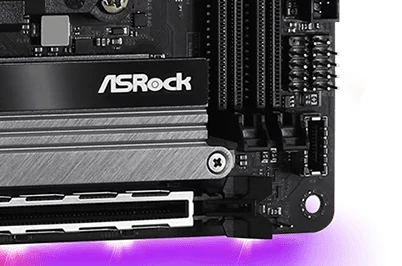
B550 adds the USB32_TC_2 front Type-C header, rated for USB 3.2 Gen2, or 10 Gb/s, in the Vermeer/Cezanne comparison. The lower-edge hardware detail shows the small front-C connection below the long expansion slot, near other front-panel connections. Check that the case lead can seat and bend there without interfering with the graphics assembly.
Both boards retain the separate front Gen1 header supporting two ports and the USB 2.0 header supporting two ports. Neither turns a case's faster front-port label into a faster motherboard connection. Match the actual lead, port capability, device and cable rather than relying on the reversible connector shape.
The B550 specification includes a boundary for older Picasso APUs: front Type-C drops to Gen1, or 5 Gb/s. That footnote does not itself confirm support for a particular older processor. Keep the present Vermeer/Cezanne selection separate from an assumption that any older AM4 CPU will work.
Check the Rear Ports and Network You Will Retain
| Connection | A520M-ITX/ac | B550 Phantom Gaming-ITX/ax |
|---|---|---|
| Rear Type-C | 5 Gb/s USB | 10 Gb/s USB |
| Wired network | Gigabit Ethernet | 2.5Gb Ethernet |
| Wireless | Dual-band 802.11ac | Dual-band Wi-Fi 6, 802.11ax |
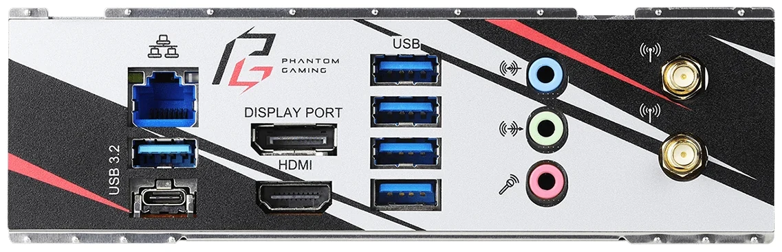
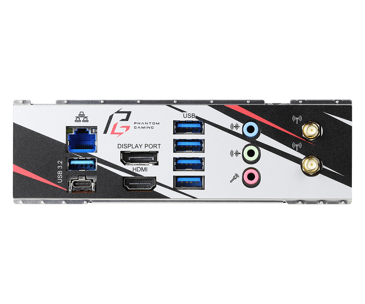
B550's rear view helps identify the Type-C socket below a Type-A port, the LAN socket above them and the antenna connections at the other end. Its faster network interfaces may be useful when moving files to another machine, but the router, switch, other endpoint and drives remain part of that transfer path. The interface labels are not measured transfer results.
Both wireless specifications concern 2.4GHz and 5GHz operation. Do not treat B550's Wi-Fi 6 label as a promise of 6GHz Wi-Fi 6E. Keep the appropriate antennas with the board and account for their position in the smaller setup.
ASRock marks this B550 model as discontinued in February 2025. Evaluate an existing board or a specific inventory offer, including condition, supplied antenna and SSD mounting pieces. Do not assume that the feature list establishes current retail availability.
Compare the Complete Retained-parts Bill
Choose A520 when one compatible M.2 SSD, four cabled SATA drives, two suitable DDR4 modules and its case connections cover the machine you actually want. Its simpler storage layout need not trigger a DDR5 purchase or replacement of working SATA drives.
Choose B550 when the second M.2 position, a required front-C connection, the applicable CPU-dependent Gen4 modes or its network interfaces solve a real limitation. Count its rear M.2 access and any required mounting hardware alongside the motherboard itself.
Before ordering either route, write down the exact CPU and BIOS, two-module memory configuration, four drive mounting positions, four data leads, PSU drive-power connections, M.2 interface assignments and the case's front leads. Finish with cooler clearance, GPU/riser space and PSU fit. Both boards list 24-pin main and 8-pin CPU power connections; those connectors alone do not establish enclosure compatibility.
A successful four-drive shrink is the complete combination of board, storage interfaces, case and cabling. Choose the board after those requirements are visible, so preserving four SATA drives does not conceal the loss of another part you meant to keep.