For a Ryzen 7000 or 9000 build, the ASRock X870 Nova WiFi favors a second CPU-connected Gen 5 SSD position, while the X870E Nova WiFi favors keeping more SATA drives and four fast M.2 positions alongside USB4. Neither is simply a five-slot board with five equivalent connections. X870 has three separate sharing conditions affecting USB4, SATA and its lower card slot. X870E's fifth M.2 position disables its lower long card slot, which is only Gen 3 x2 even when available.
Choose by assigning the actual drives, second card and external devices together. If you need four M.2 SSDs, four SATA connectors and USB4, X870E has a documented configuration using M2_1 through M2_4. If a chipset-connected Gen 4 x4 card is essential, X870 provides that lower connection while M2_5 is empty. Its two SATA ports also require M2_3 to remain empty.
1. Set the CPU and Complete Retained-parts Baseline
The main allocation below is for Ryzen 7000/9000, where both boards list the primary GPU connector, PCIE1, at up to PCIe 5.0 x16 and the first SSD position at up to Gen 5 x4. Both are AM5 ATX boards, approximately 305 × 244mm, with four DDR5 memory sockets and a published maximum capacity of 256GB. Check the exact CPU, BIOS and memory configuration before treating retained parts as compatible.
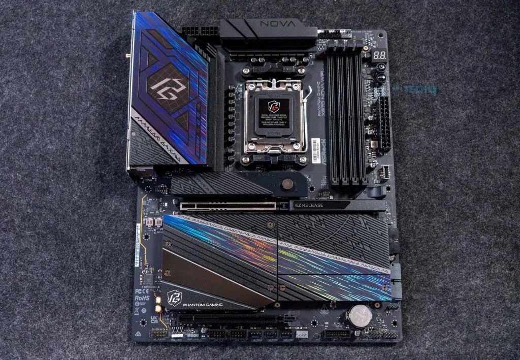
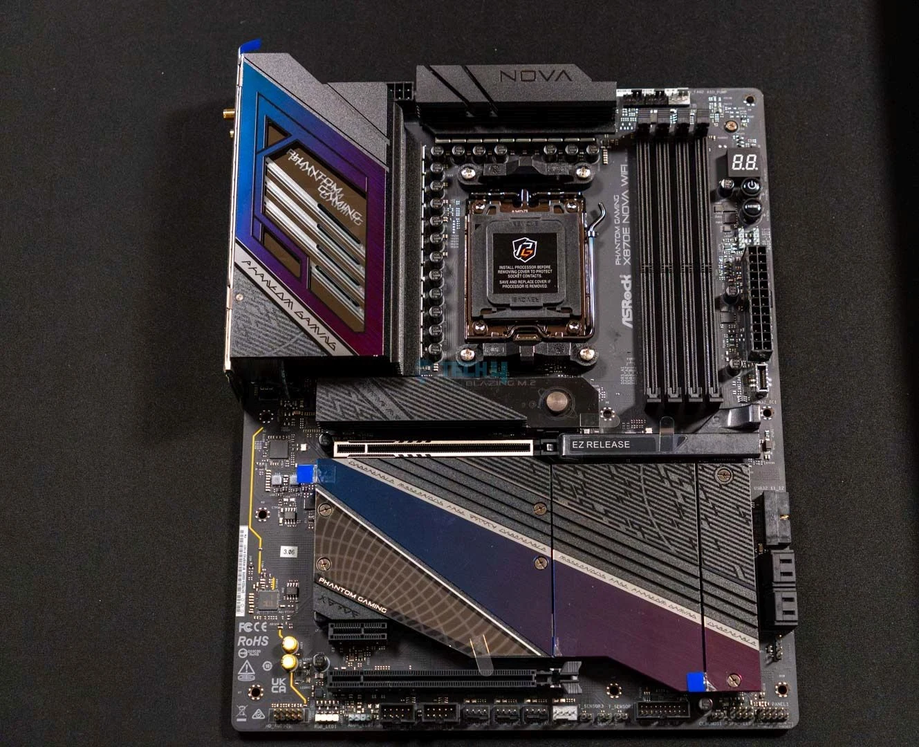
For ordinary non-ECC, unbuffered DDR5, use the actual kit's compatibility information rather than the boards' highest advertised overclocked rates. Four sockets preserve a possible four-module arrangement; they do not guarantee four modules at that headline setting. The complete-board photographs also show the large storage heatsinks and lower-card regions that must fit around the retained GPU.
Ryzen 8000 requires a separate allocation check. ASRock lists the main GPU connection at Gen 4 x8 for Phoenix 1 and Gen 4 x4 for Phoenix 2, and M2_1 at Gen 4 x4. X870 additionally specifies a Gen 4 x2 USB4-controller connection with Phoenix 2. Do not carry the following 7000/9000 storage plan into an 8000 build without checking the exact CPU's PCIe/M.2 bandwidth table.
2. Compare All Five SSD Positions, Including the Slow One
Every listed M.2 storage position on both boards supports 2280 length. A retained 2242 or 2260 drive therefore needs another arrangement; its connector shape alone does not establish a supported mounting position here. The separate Key E wireless socket is not a sixth SSD position.
| Position | X870 Nova | X870E Nova |
|---|---|---|
| M2_1 | CPU: Gen 5 x4 | CPU: Gen 5 x4 |
| M2_2 | CPU: Gen 5 x4 maximum; shares with USB4 | Chipset: Gen 4 x4 |
| M2_3 | Chipset: SATA or Gen 3 x2; disables both SATA connectors | Chipset: Gen 4 x4 |
| M2_4 | Chipset: Gen 4 x4 | Chipset: Gen 4 x4 |
| M2_5 | Chipset: Gen 4 x4; reduces lower card to x2 | Chipset: SATA or Gen 3 x2; disables lower long card |
ASRock gives M2_1 first installation priority on both boards. X870's M2_2 is its second Gen 5-capable position, but its maximum is conditional. X870E instead provides three chipset-connected Gen 4 x4 positions at M2_2, M2_3 and M2_4.
The mixed SATA/PCIe position moves between models: M2_3 on X870, M2_5 on X870E. Those are the places to consider for a compatible 2280 M.2 SATA drive. They also support PCIe Gen 3 x2, so even an all-NVMe five-drive plan includes a slower connection. A Gen 4 x4 SSD placed there cannot receive a Gen 4 x4 link.
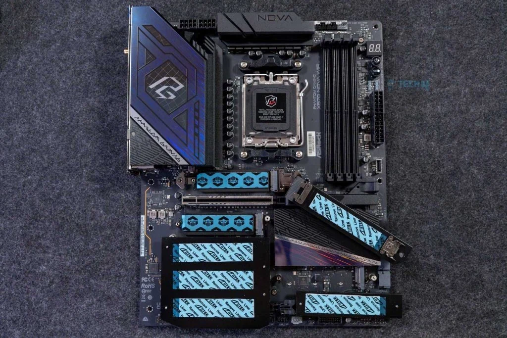
The X870 photograph with storage heatsinks lifted helps expose the covered SSD area. It is an identification view, not an instruction to operate the board with the thermal-pad films or loose heatsinks left as photographed. Use the selected drive's compatibility information and the board's installation instructions.
3. Decide Whether X870’s Second Gen 5 Position Is Worth the USB4 Tradeoff
On X870, occupying M2_2 puts M2_2 and the rear USB4 connection into the documented x2 sharing arrangement. ASRock also provides a BIOS option to give M2_2 x4, but that disables both USB4_TC1 and USB4_TC2. The original block-diagram detail shows the CPU, switch/redriver and ASMedia USB4 host-controller path.
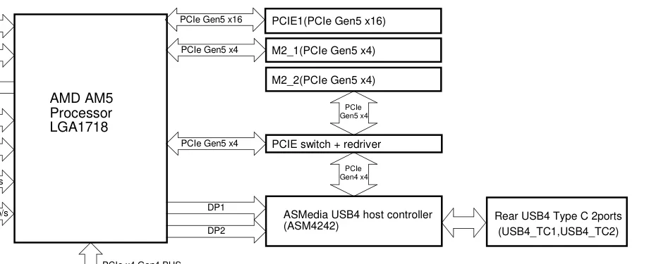
There are therefore three useful planning states: leave M2_2 empty and retain the USB4 controller's unshared host connection; occupy M2_2 and accept the shared arrangement; or select M2_2 x4 in BIOS and give up both rear USB4 ports. Write the intended state beside that SSD before purchasing the board or another drive.
For example, if a retained USB4 dock or external SSD is essential, do not select the M2_2 x4 BIOS arrangement and expect one rear USB4 port to remain available. If the second CPU-connected SSD matters more and those ports are unnecessary, the x4 option may fit the build.
The x2 statement concerns the documented lane arrangement. It is not a measured SSD transfer result or a guarantee that every connected USB4 device delivers a particular throughput. Keep the controller's host connection, the external device's protocol and the device's actual performance separate.
X870E's documented M2_2 connection is chipset Gen 4 x4, and its published sharing condition concerns M2_5 and PCIE3, rather than M2_2 and USB4. That makes the first four SSD positions a different proposition for someone retaining USB4 peripherals.
4. Keep SATA Connectors by Leaving the Right M.2 Position Empty
X870 has two SATA 6Gb/s connectors, SATA3_1 and SATA3_2. Its rule is occupancy-based: if M2_3 is occupied, both are disabled. That applies when planning an M.2 SATA drive there as well as a PCIe drive; changing the drive protocol does not remove the stated condition.
For example, retaining two SATA drives means leaving M2_3 empty. The remaining M.2 candidates are M2_1, M2_2, M2_4 and M2_5, but they still carry the separate USB4 and lower-card conditions. You have not obtained four independent, unrestricted SSD positions merely by preserving the SATA connectors.
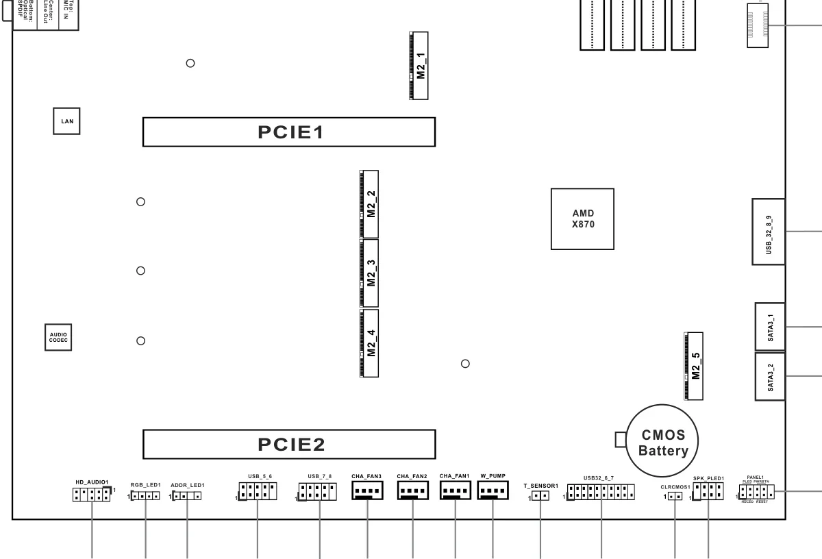
The original lower-board layout identifies M2_3 between the other covered storage positions and the two SATA connectors at the right edge. Assign the slot by its printed name; the third drive you install does not necessarily belong in the connector named M2_3.
X870E lists four SATA connectors: two through the chipset and two through ASMedia ASM1061. The manual identifies the extra pair as SATA3_A1 and SATA3_A2. Keep that controller distinction in the drive plan rather than assuming all four ports form one chipset-controlled array.
Both specifications list SATA RAID 0/1 and NVMe RAID 0/1/10, but those summaries do not establish a unified array spanning unlike SATA controllers. For ordinary retained SATA drives, first establish the actual ports, data cables, PSU connections and case mounts; an array migration needs its own controller-specific compatibility check.
5. Reserve the Lower Card Slot Before Filling the Fifth SSD Position
On X870, the lower long connector is PCIE2, chipset Gen 4 x4. Occupying M2_5 reduces it to Gen 4 x2. A retained card that requires x4 therefore needs M2_5 left empty, plus a physical fit check beneath the GPU.
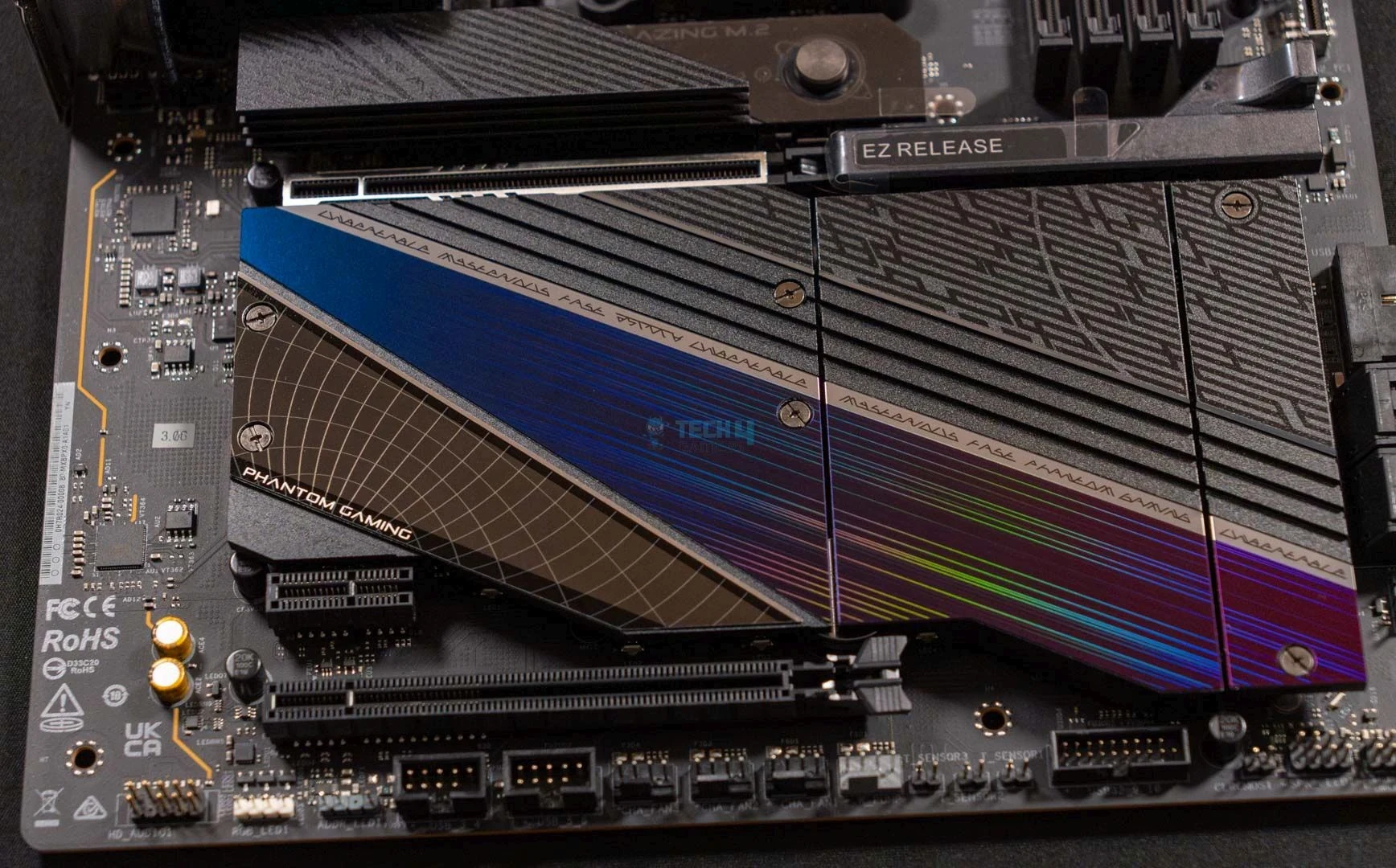
On X870E, the lower long connector is PCIE3, chipset Gen 3 x2. Occupying M2_5 disables it completely. It is not an x4 alternative to X870's lower connector just because both are long slots. X870E also lists a separate PCIE2 Gen 3 x1 position, visible above the long lower slot in the detail photograph.
That small connector is useful only if the actual retained card accepts its electrical connection and physically fits. It does not satisfy a card's requirement for four lanes. Likewise, leaving X870E's M2_5 empty restores its listed Gen 3 x2 connector, not a Gen 4 x4 connection.
Check the GPU cooler's occupied space, the other card's bracket and height, and the case's expansion openings. A free connector in the electrical plan may still be covered by the GPU. Neither board provides a CPU-connected secondary card slot in these documented lower positions.
6. Choose One Simultaneous Configuration, Then Assign Rear Devices
The following are conditional allocations from the published slot and sharing rules, for Ryzen 7000/9000. They describe what to reserve electrically, not an installation or throughput test.
| Requirement | X870 Nova allocation | X870E Nova allocation |
|---|---|---|
| SATA, unshared USB4 host path and lower card | M2_1 and M2_4 only; lower card Gen 4 x4 | M2_1 through M2_4; lower card Gen 3 x2 |
| Four M.2 drives plus SATA | Skip M2_3; USB4 and lower-card tradeoffs apply | Use M2_1 through M2_4 |
| All five M.2 positions | No SATA connectors; lower card x2; USB4 shared or disabled | Lower long card disabled; fifth SSD SATA or Gen 3 x2 |
For example, suppose you want to retain three suitable 2280 M.2 drives, two SATA drives and a card requiring an electrical x4 connection. On X870, assign the SSDs to M2_1, M2_2 and M2_4, leaving M2_3 empty for SATA and M2_5 empty for the lower card. Keeping rear USB4 means accepting M2_2's shared arrangement; selecting that SSD's x4 BIOS mode sacrifices both USB4 ports. The card still needs a physical clearance check. X870E can assign three drives among M2_1 through M2_4 while retaining SATA and USB4, but its lower Gen 3 x2 connector does not satisfy that card's four-lane requirement. That complete requirement can therefore decide the board before price or a fifth drive enters the discussion.
Do not compare the first row as equal lower-card performance: X870 retains Gen 4 x4 there, while X870E retains only Gen 3 x2. Also decide whether the slower mixed-protocol position is acceptable before treating either five-drive arrangement as the goal.
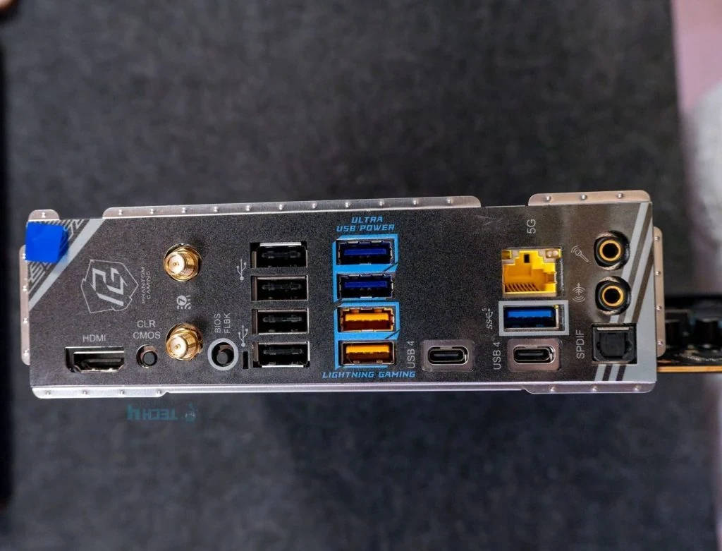
Both boards list two rear USB4 Type-C ports up to 40Gbps, with USB PD up to 5V/3A, 15W. The actual X870 rear photograph shows both Type-C positions and the adjacent Type-A groups. Its USB4 availability still depends on the M2_2 allocation above.
For display use, both specifications say USB4 carries only the CPU's embedded graphics, with listed modes up to 8K at 30Hz. Their HDMI specification reaches 4K at 120Hz, subject to CPU support. Check the actual processor's graphics, monitor and cable rather than expecting the discrete GPU's output to appear automatically through motherboard USB4.
7. Match the Remaining USB Ports and Front-panel Cable
The rear Type-A mix is different even before considering USB4 sharing.
| Rear Type-A group | X870 Nova | X870E Nova |
|---|---|---|
| 10Gbps | Two | Five |
| 5Gbps | Three | Three |
| USB 2.0 | Four | Two |
X870 therefore offers nine rear Type-A ports, while X870E offers ten with more 10Gbps positions. Assign retained external drives and ordinary peripherals to suitable ports; connector count alone does not establish the fastest connection for each device.
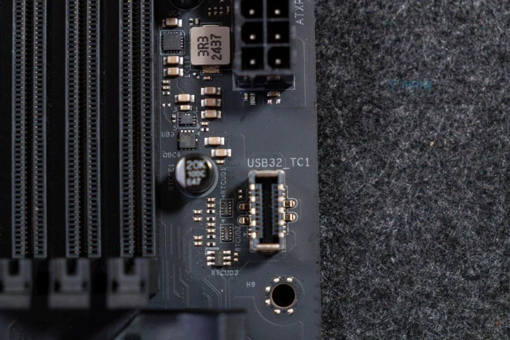
Both boards provide one front Type-C header up to 20Gbps, two 5Gbps headers supporting four front Type-A ports, and two USB 2.0 headers supporting four ports. The X870 detail photograph clearly identifies its USB32_TC1 header beside the memory and main power connector. Match the case's actual front cable to that connector.
X870 explicitly specifies USB PD 3.0 up to 12V/3A, 36W at its front Type-C header. X870E's corresponding specification lists the 20Gbps connection without that same 36W claim. Do not transfer the charging figure between models; check the exact board, case connection and device before making charging capability a purchase requirement.
Both list 5Gb Ethernet and Realtek ALC4082 audio. Their general operating-system lists include Windows 10/11, but the current wireless specifications state that Wi-Fi 7 requires Windows 11 and that 6GHz availability depends on regional rules and updates. A general OS listing does not cancel those wireless conditions.
8. Finish the Parts List Around the Selected Allocation
For either board, account for the 24-pin main power connection and two 8-pin 12V CPU-power connectors, the GPU's own power requirements, and appropriate PSU cables. Both list two CPU-fan headers, three chassis-fan headers, an AIO-pump header and a water-pump header; map actual cooling connections without treating connector count as an unlimited power budget.
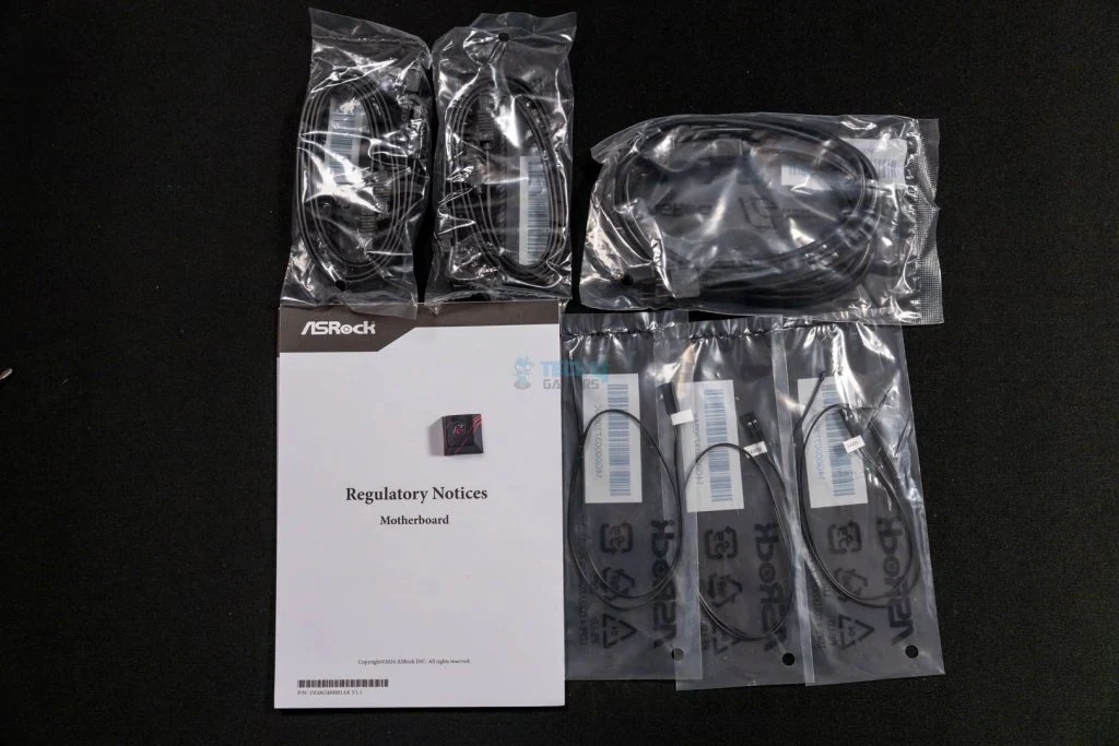
The listed accessories differ. X870's specification lists two SATA data cables, two Wi-Fi antennas, one ARGB splitter and one thermistor cable. X870E lists four SATA data cables, one Wi-Fi antenna, one ARGB splitter and three thermistor cables; it also has three thermistor headers versus X870's one. The manuals mark package accessories optional, so confirm the actual unit rather than assuming every regional package is identical.
The X870E accessories photograph helps identify the separate cable bundles. Match the required SATA leads to the selected ports and drives, not to a five-M.2 headline. In the SSD areas, follow the correct manual section for the heatsink and mounting lock, remove the specified thermal-pad protective films and avoid overtightening the heatsink screws.
Choose X870 when its second CPU-connected SSD option or available Gen 4 x4 lower card connection matters enough to plan around all three sharing rules. Choose X870E when four x4-linked M.2 positions, four SATA connectors and USB4 serve the complete configuration, while its slower lower card slot is sufficient or unnecessary. Add the fifth SSD only after accepting what that exact position changes.