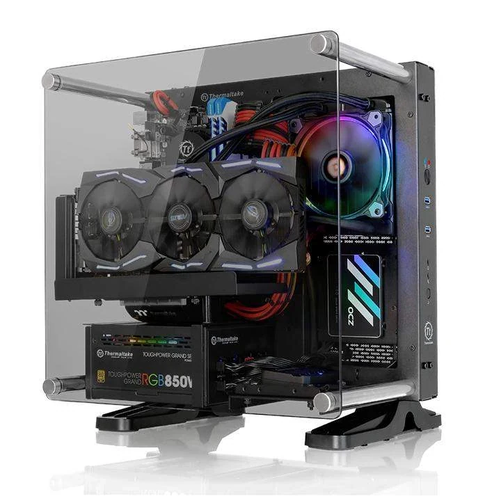
A Thermaltake Core P1 TG can be a candidate for moving an existing Mini-ITX system into an open frame, but “supports 240 mm” is not a complete cooling compatibility check. Start with the radiator's actual body width, bare thickness, overall length, fittings and installed fans. Then check that assembly against the chosen GPU position and the other parts you want to keep.
For the CA-1H9-00T1WN-00, Thermaltake's current US specification lists a 122 mm radiator-width limit and qualifies its 380 mm GPU figure with radiator thickness “under 30mm without fan.” Other passages and the original manual do not agree on every limit. Those disagreements belong in the purchase decision; they cannot be solved by selecting the largest number.
The useful outcome is a complete conditional parts list: what remains a candidate for reuse, what mounting hardware is missing, and which specific combinations still need confirmation before ordering. A disputed GPU or boundary-size radiator need not stop every other part of that assessment.
Identify the Exact Frame and Complete Kit
This guide concerns the Core P1 TG Mini ITX, not another Core P enclosure with a similar appearance. Match the part number on the actual case or listing. The US product page identifies this model as discontinued, making the contents of a particular remaining or used kit especially relevant.
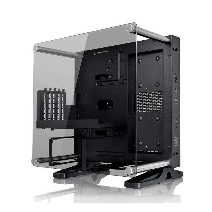
The published motherboard format is 6.7 × 6.7 inches, Mini-ITX. An existing ATX or Micro-ATX board does not become eligible because the case is open. The listed external dimensions are 422 × 332 × 380 mm in height–width–depth order; include the eventual placement and connected leads when assessing your desk space.
Compare an actual kit photograph with the manufacturer's empty-frame view. Account for the glass panel, its posts and fasteners, GPU bracket assembly, PSU supports, drive carriers and intended feet. An enclosure shell without these pieces may cost more to complete than the advertised case price suggests. Keep the motherboard's own power and header requirements on the list as well.
Measure the Radiator Body Rather Than Its Fan Class
The 240 mm designation describes the supported two-120 mm fan class. It does not say that the complete radiator is exactly 240 mm long or that all products in that class have the same width and thickness.
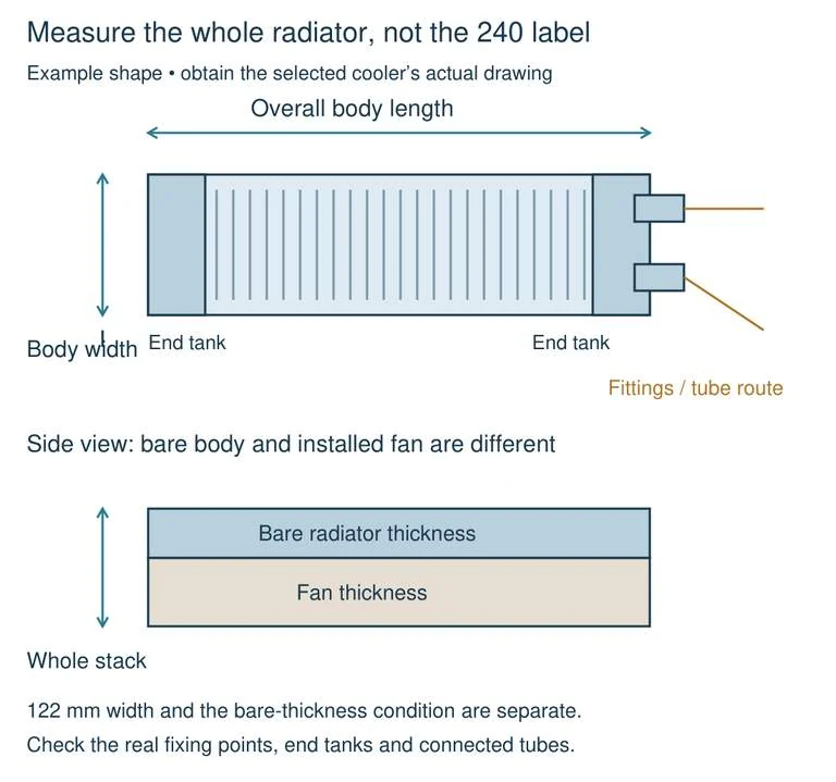
Obtain the selected cooler's dimension drawing and identify the overall radiator body, including both end tanks. Record its largest body width, bare thickness, mounting-hole arrangement and total length. Locate the fittings and the space the connected tubes need at the chosen end. A listing that supplies only the nominal class leaves those checks unfinished.
Use Thermaltake’s published 122 mm width for a first screen. For example, a hypothetical 121 mm-wide body is below that figure, while a 124 mm body exceeds it. Passing the width comparison does not establish that the end tanks, fittings, screws or connected tubes clear the frame.
The manual introduces an additional boundary issue: its radiator drawing says less than 122.5 mm, while the same page's caption and the current product table say 122 mm. Do not use the more permissive drawing annotation to approve a 122.3 mm candidate without resolving that difference for the actual installation.
Read the Chassis Opening in the Original Drawing Correctly
The cooling illustration labels a chassis opening with 306.8 and 123 mm dimensions. Those arrows refer to the illustrated frame geometry; they are not a blanket statement that every radiator with that outer length and width will fit.
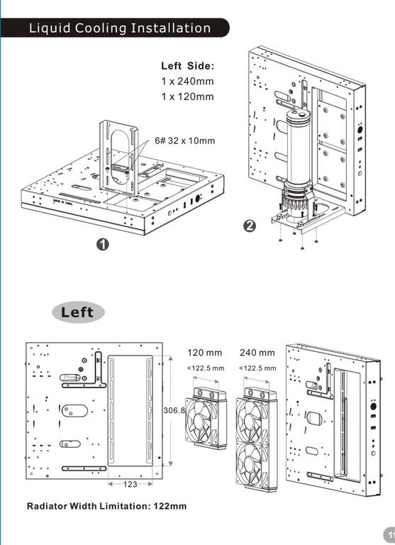
Keep three things separate: the frame opening, the radiator's external envelope, and the fixing points that must align. A radiator can be narrower than an opening yet have unsuitable mounting positions or a fitting that projects into an obstruction. Conversely, a nominal size tells you nothing about those particular endpoints.
Place the actual overall-length and fitting information alongside the original mounting view. Check which end faces the motherboard, GPU and PSU cables in the intended arrangement. Include room to connect and route the tubes without relying on an empty-case photograph as proof that a filled assembly will work.
Thermaltake describes native AIO support for one 120 mm or one 240 mm arrangement without an additional bracket. Those are alternatives in the supported cooling area, not two independent radiator spaces to add together. The separate pump/reservoir illustration is another arrangement to understand, rather than evidence that a complete custom loop is supplied with the case.
Add the Fans Before Comparing the Cooling and GPU Spaces
Thermaltake's radiator table says thickness “up to 30mm without fan,” whereas the GPU-clearance condition uses under 30 mm without fan. The wording differs at exactly 30 mm. Treat a boundary-size candidate as unresolved instead of silently converting both statements into one inclusive rule.
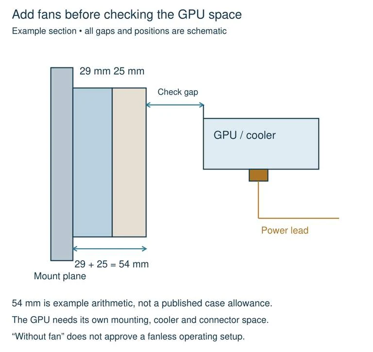
The bare-radiator figure also excludes the fans. For example, a hypothetical 29 mm radiator with a 25 mm fan has a 54 mm nominal body-and-fan stack before accounting for projecting hardware or fittings. That arithmetic describes the assembly you must place; it does not create a published 54 mm clearance allowance.
Check where the complete stack projects relative to the GPU, its power connectors and the selected mounting arrangement. The “without fan” qualification is not an instruction to operate an otherwise fan-cooled system without fans to recover GPU space.
For an existing AIO, retain the correct CPU-socket hardware, fans and intended fasteners as part of the same decision. A radiator that passes a body-width screen is not useful if the cooler cannot mount to the retained board or its tubes cannot reach the CPU position.
Choose the GPU Mounting Method Before Approving Its Length
The original manual illustrates direct installation into the motherboard and an extended arrangement using a riser cable and the case's PCI bracket hardware. Choose the intended arrangement before treating a GPU length as meaningful.
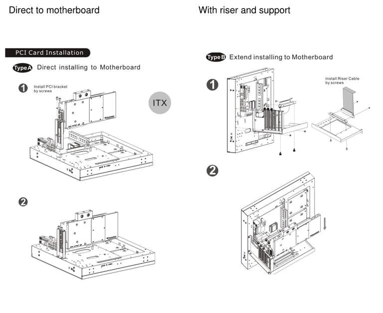
For either layout, compare the full card length from its rear bracket seating reference to its furthest forward projection. Include the actual cooler rather than using PCB length alone. Also check card thickness, the bracket's fixing points and the clearance required by its power leads.
The current product page says a standard riser cable is included. It separately advertises optional TT Premium PCI-E 3.0 extenders; that optional listing does not establish the supplied cable's suitability for every modern board and GPU combination. Thermaltake expressly declines to guarantee that the included standard riser suits a particular system without further testing.
If retaining a riser, verify its exact connectors, routing, mounting and compatibility. If choosing direct installation, retain the appropriate bracket arrangement rather than adding a riser solely because one appears in a display build. The case's five expansion positions do not create five independent motherboard PCIe slots.
Keep the Conflicting GPU and Cooler Limits Visible
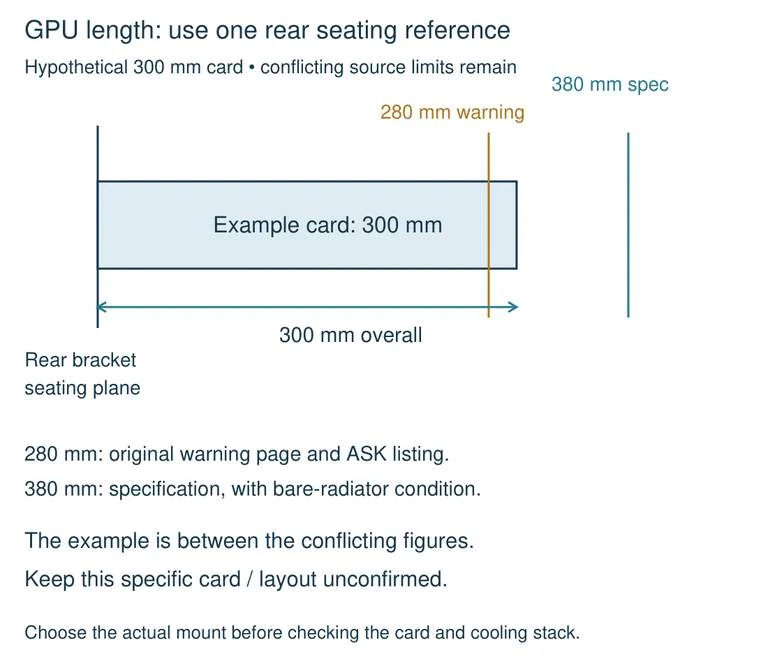
The manufacturer's specification table, current US page and 2022 catalog give a 380 mm GPU figure. The table attaches the bare-radiator condition discussed above. The same original manual's warning page instead states 280 mm. ASK's Japanese listing for the same part number also gives 280 mm and describes the supported bracket/riser arrangement.
The CPU-cooler figures disagree in the opposite direction: the current table, catalog and ASK list 170 mm, while the original warning page states 180 mm. Neither disagreement proves that one number is a typo or identifies a confirmed configuration in which the larger number applies.
| Check | Published statements | Practical first decision |
|---|---|---|
| GPU length | 380 mm in specifications; 280 mm in the warning and ASK listing | A card above 280 mm remains in the disputed region; do not approve it from the 380 mm line alone |
| CPU-cooler height | 170 mm in specifications and ASK; 180 mm in the warning | A cooler above 170 mm needs the actual configuration and height reference resolved |
| Radiator width | 122 mm caption/specification; less than 122.5 mm drawing | Do not approve an intermediate-width body solely from the larger annotation |
| Bare radiator thickness | Under 30 mm for the GPU condition; up to 30 mm in cooling prose | Resolve an exactly-30 mm candidate and check its complete fan stack |
The lower figures can help identify candidates that avoid a particular numerical dispute. They are not a newly confirmed universal set of hard limits, and falling below them does not certify simultaneous fit.
For example, a hypothetical 300 mm card exceeds 280 mm but is shorter than 380 mm. Its correct purchase status is not yet confirmed, with the exact card, bracket arrangement, cooling stack and case revision identified for follow-up. Confirm those details before committing to the case or replacing the card.
Check the Air-cooler Height from the CPU Contact Surface
If retaining air cooling instead of an AIO, measure the complete cooler from its CPU contact surface to its highest part, including the installed fan. The case's external dimensions and an empty gap in a photograph are not substitutes for that measurement.
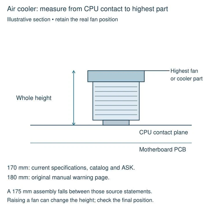
Compare the actual assembled height with the conflicting 170/180 mm statements, keeping their source attribution. A hypothetical 165 mm cooler is below both stated figures; a 175 mm cooler falls between them and needs further confirmation. The first example still needs the correct socket kit and clearance around the retained RAM, board components and glass.
Raising a cooler fan to clear tall memory can change the highest point. Use the final fan position rather than the cooler's default catalog height. This is a physical screen; it does not establish that a particular cooler handles the selected processor's workload in the finished arrangement.
Retain the PSU Together with Its Support and Cables
The published PSU length is 180 mm, and the case uses a standard PS2/ATX supply. Measure the retained PSU body, then account separately for its plugs, cable exits and the space occupied by the other components.
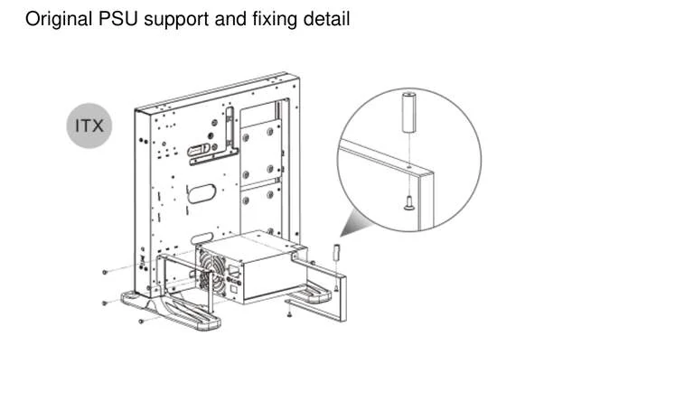
The original installation drawing shows the PSU placed in position and its supporting bridge adjusted and secured. Inspect both the rear fixing arrangement and that support in a used kit. A rectangular opening beneath the GPU is not a complete PSU mount when its support pieces or fasteners are absent.
Retain only the correct cable set for the actual PSU. Include motherboard main and auxiliary power, GPU power where required, and drive power. Physical support for an ATX unit cannot supply a missing electrical connection, establish adequate capacity or make another modular PSU's cables interchangeable.
Allocate Actual Drive Carriers Instead of Adding Every Maximum
The current specification lists two exterior 2.5-inch positions, one internal position shared between a 3.5-inch and a 2.5-inch drive, and one further internal 2.5-inch position. On that inventory, the shared position takes one choice, not both drives simultaneously.
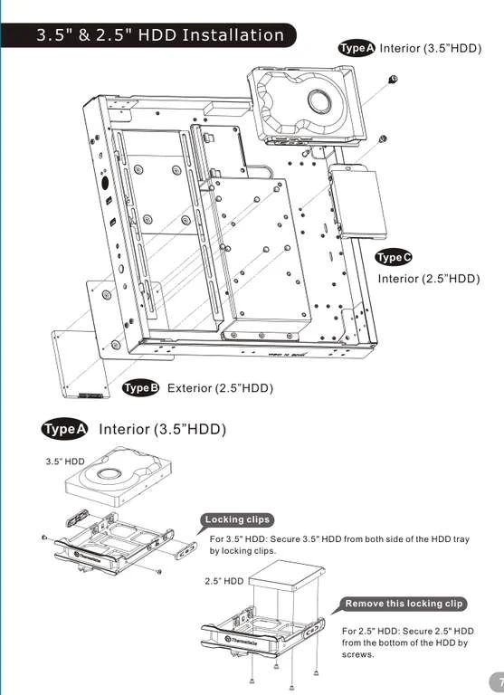
The original manual's specification table labels the exterior positions as 3.5-inch, but its installation illustration identifies the exterior Type B arrangement as 2.5-inch. The current US table and ASK listing also identify exterior 2.5-inch positions. Do not turn the inconsistent older table into an order for extra exterior HDD hardware.
The native carrier drawings help distinguish locations and fastening methods. The illustrated Type A tray uses side locking clips for a 3.5-inch drive; its 2.5-inch method removes the indicated clip and uses bottom screws. Other trays slide out for fastening and return to their carriers. Keep those actual carriers and suitable screws with the retained drives.
Map the chosen drives against the cooling arrangement before counting them as retained. The front-facing mounting area, radiator, fans and connected leads must be checked together; individually listed drive and cooling maxima do not prove their coexistence. Count a SATA data path and power connection for each retained SATA drive, and inspect the rear routing space with the occupied carriers in place.
Include the Glass and Desktop Supports
The glass panel and its supports belong in the assembled layout. Use the original window-installation view to identify the posts and fixing points rather than treating the glass as a loose decorative cover.
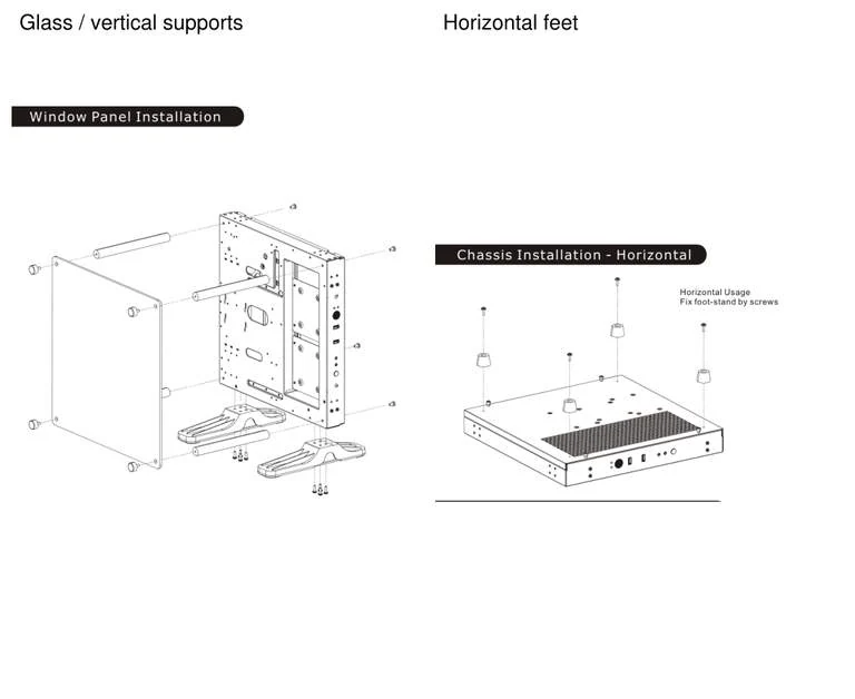
For desktop placement, distinguish the vertical supports from the horizontal foot-stand arrangement shown in the manual. Inspect the feet and screws needed for your chosen orientation. The horizontal installation changes how the chassis rests; it does not remove the component-clearance and connection checks above.
Wall mounting is an optional arrangement, and the wall bracket is not included. The manual supplies mounting information, but that does not determine the correct bracket, wall fixings or supported load for your finished computer. Leave those questions unresolved unless the actual support arrangement is established.
Keep the Front Panel Working with the Retained Board
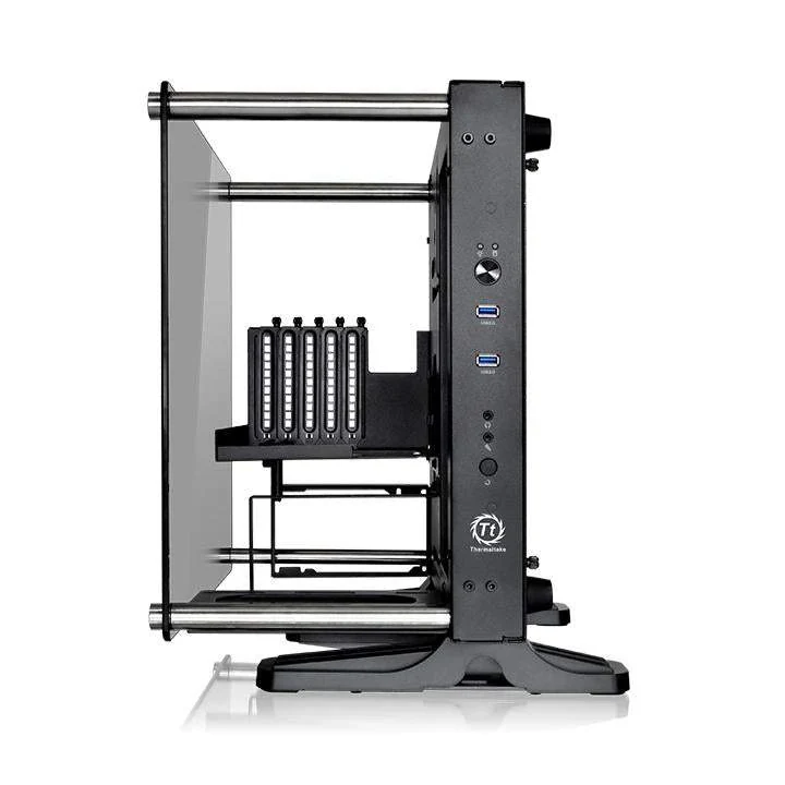
The front panel provides two USB 3.0 ports and audio connections. Match the case's internal USB, audio, switch and indicator leads to the retained motherboard's headers. A working rear USB socket is not a substitute for a missing internal front-panel connection. Check the board manual for the corresponding internal headers, then inspect the case leads and plugs. Keep the switch and indicator connections identified separately from USB and audio; they do not share one interchangeable connector. The actual front-panel photograph is useful for checking that the ports and controls belong to the supplied case, while the internal leads still need their own inspection.
Price the Complete Retained-parts Arrangement
Compare the case and its missing pieces as one purchase. Decide whether you are keeping an air cooler, an AIO or a separately specified custom loop; do not add the hardware costs of every alternative to one compulsory bundle.
| Part of the move | Candidate for reuse | Resolve before ordering |
|---|---|---|
| Motherboard and CPU | Existing Mini-ITX platform | Correct cooler socket hardware, power inputs and front-panel headers |
| Cooling | Actual air cooler or selected 120/240 AIO | Height or complete radiator envelope, fixing points, fan stack and tube route |
| GPU | Exact retained card | Direct/riser arrangement, bracket support, power leads and any disputed length branch |
| PSU | Suitable ATX unit within the body-length screen | Supporting bridge, correct cables, plugs and usable routing space |
| Storage | Identified drives in actual carriers | Shared position choice, cooling interaction, fasteners, data and power |
| Placement | Complete glass and desktop hardware | Posts, feet and screws; separate wall-support decision only if required |
A radiator advertised as 240 mm is therefore only the beginning. Proceed when the whole arrangement has usable fixing points, complete connections and a supported dimensional screen. Keep a 300 mm GPU, a boundary-width radiator or another disputed part explicitly pending until its exact arrangement is resolved.