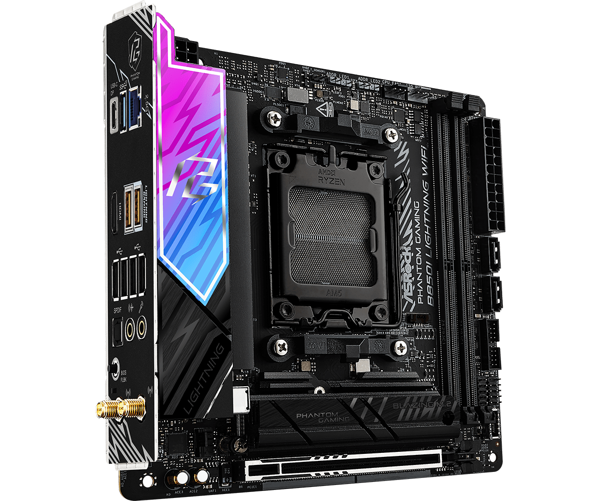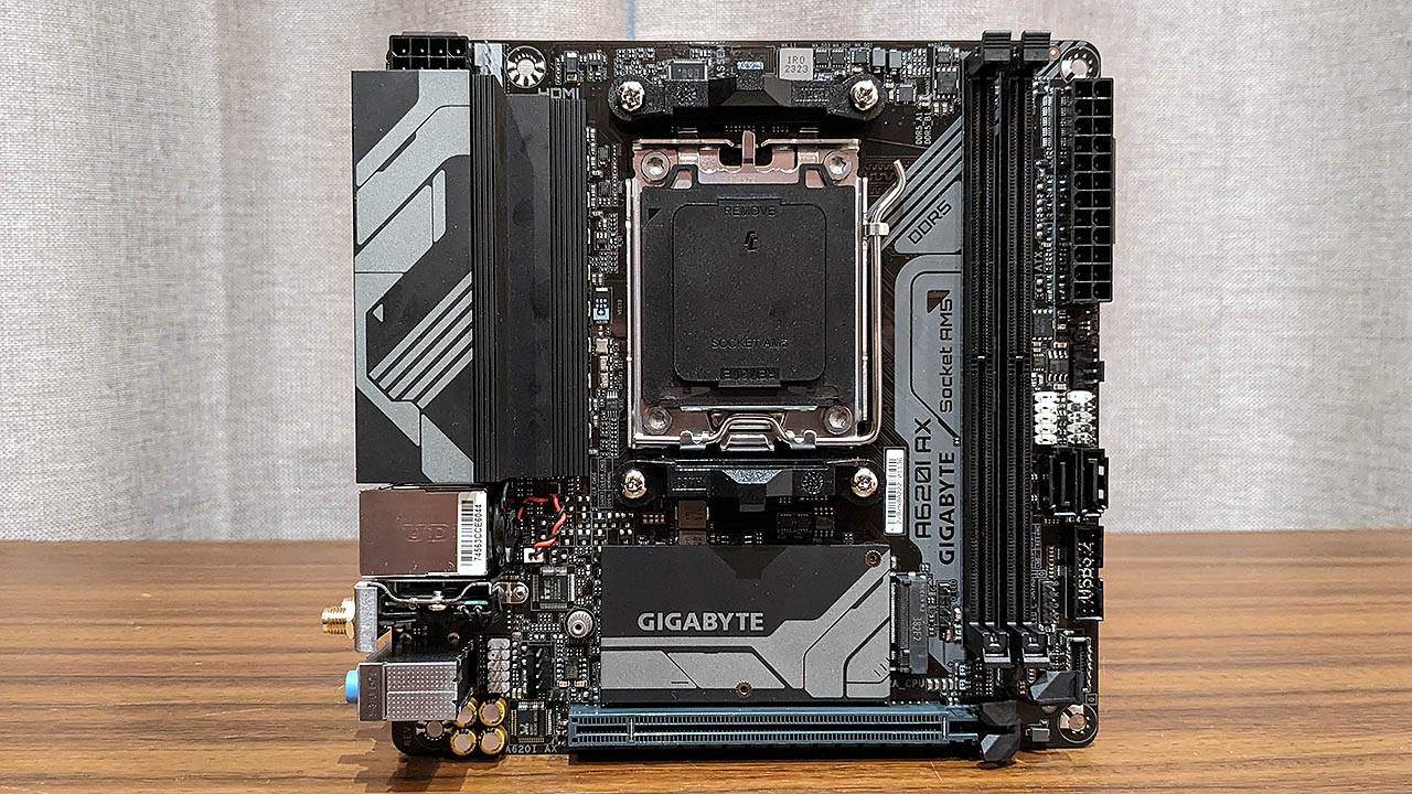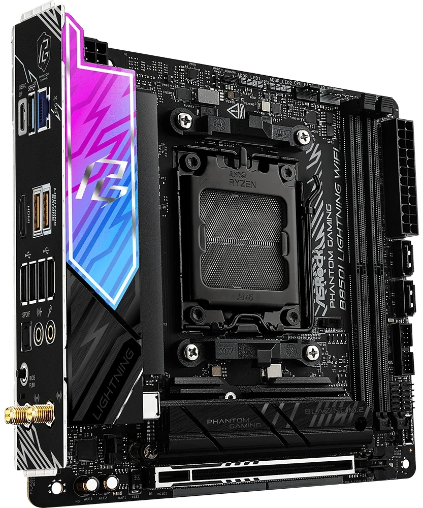
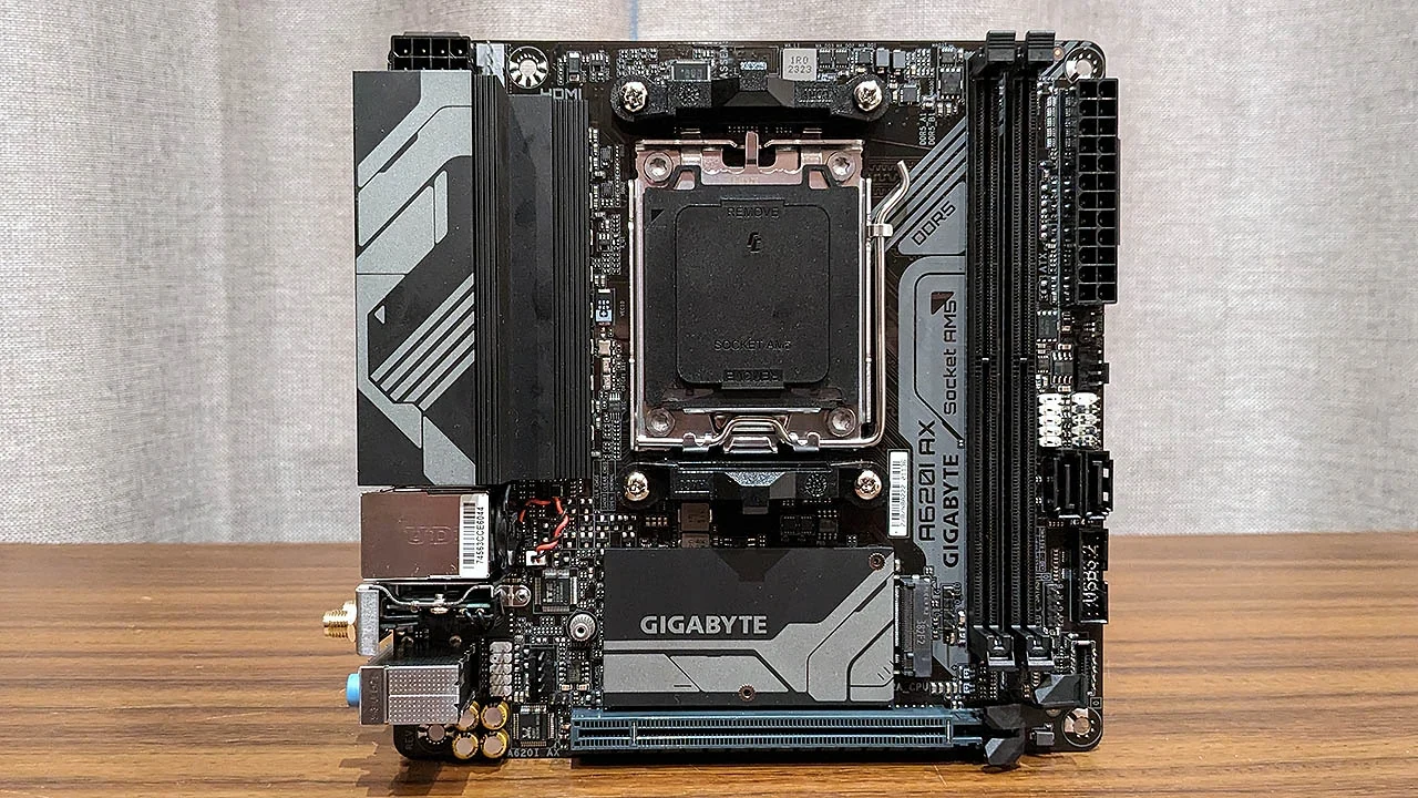
For an AM5 desktop moving to Mini-ITX, the GIGABYTE A620I AX rev.1.0 and ASRock B850I Lightning WiFi offer two different storage plans. The A620I AX has one onboard M.2 position; the B850I has two. Both provide two DDR5 sockets, two SATA ports and a 5Gbps front Type-C header. Keeping a second NVMe SSD and a graphics card therefore changes the choice more directly than the chipset name alone.
Start with a list of the CPU, GPU, memory modules, drives and case leads you actually want to retain. The comparison below uses the A620I AX's exact rev.1.0 specification. Check the revision printed on the board or offered unit before applying it to a purchase; another A620I AX revision is a separate verification.
Match the CPU Family to the Graphics Slot
Both boards list Ryzen 7000, 8000 and 9000 processor support, but CPU compatibility and graphics-slot bandwidth are separate entries. Record the full CPU model and required BIOS, then match its processor family to the manufacturer's bandwidth information. Do not classify an 8000-series chip from its Ryzen retail tier alone.
| Retained CPU family | A620I AX rev.1.0 graphics slot | B850I Lightning WiFi graphics slot |
|---|---|---|
| Ryzen 7000 | PCIe 4.0 x16 | PCIe 5.0 x16 |
| Ryzen 8000, Phoenix 1 | PCIe 4.0 x8 | PCIe 4.0 x8 |
| Ryzen 8000, Phoenix 2 | PCIe 4.0 x4 | PCIe 4.0 x4 |
| Ryzen 9000 | CPU support is listed; no separate 9000 graphics-slot row is supplied | PCIe 5.0 x16 |
A full-length slot is not proof of a full x16 connection with every CPU. Moving a Phoenix 2 processor from one of these boards to the other does not turn its published Gen4 x4 graphics connection into x16. Likewise, the B850I's headline Gen5 slot applies at Gen5 x16 with the listed 7000 and 9000 families, not universally to Ryzen 8000.
The missing A620I AX 9000 row needs to remain a purchasing question. Its CPU list includes that generation, but the detailed expansion and M.2 rows name 7000 and the two Phoenix groups. Confirm the exact 9000 configuration rather than copying the 7000 bandwidth row into it. For either board, also establish that the unit's installed BIOS supports your particular CPU.
These are published link arrangements. They do not quantify the frame-rate effect on your retained graphics card or establish compatibility with a particular riser and small case.
Use the A620I AX for a Genuinely single-M.2 Plan
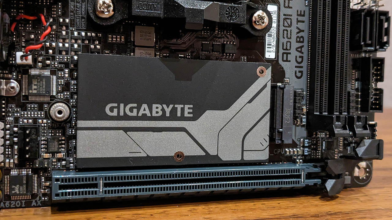
The A620I AX's CPU-connected storage connector accepts 2280 M-key PCIe SSDs. Its listed 7000, Phoenix 1 and Phoenix 2 rows specify support for PCIe 4.0 x4/x2 SSDs. That is one physical connector, with two separate SATA connections alongside it. The x4/x2 SSD-support wording does not describe two separate M.2 positions.
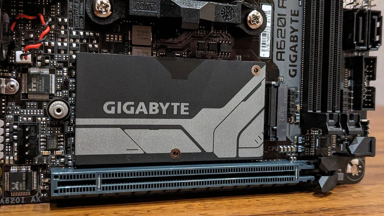
For example, a compatible CPU, one supported 2280 PCIe SSD, a graphics card and retained SATA storage form a sensible allocation to investigate. Name the SSD going into the M.2 connector and count the SATA devices, their case bays, data cables and PSU power connections separately. The SATA ports do not provide another native NVMe position.
A two-NVMe inventory needs a different decision. GIGABYTE says the board's sole long PCIe slot supports a graphics card or an NVMe SSD. Treating an expansion adapter as a free second M.2 position would spend the slot already reserved for the GPU. Do not assume that a splitter or bifurcation accessory restores both functions without a verified configuration.
The close-up helps locate the storage area between the memory edge and expansion slot. Check the actual SSD assembly, including any attached cooler, against the surrounding components. A photograph of a nearby board heatsink does not establish that your SSD's own heatsink clears the GPU or CPU cooler.
Use the B850I’s Second Onboard Socket Without Spending the GPU Slot
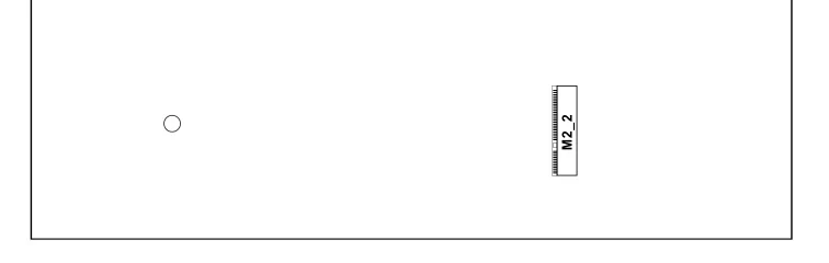
The B850I provides two distinct onboard SSD routes. M2_1 is CPU-connected and is ASRock's first-priority installation position. M2_2 is chipset-connected and sits on the back of the motherboard. The back-side detail below shows its M2_2 connector and mounting point near the board edge. Use that label rather than treating the front-facing wireless socket as the second SSD position.
| Storage route | Connection and supported length | Retained-parts implication |
|---|---|---|
| A620I AX onboard M.2 | One CPU-connected 2280 PCIe Gen4 position; x4/x2 SSDs listed for the named 7000/Phoenix groups | One onboard PCIe SSD alongside the graphics card |
| B850I M2_1 | 2280; Gen5 x4 with Ryzen 7000/9000, Gen4 x4 with Phoenix 1/2 | Match the CPU before crediting a Gen5 connection |
| B850I M2_2 | Chipset-connected 2280 PCIe Gen4 x4 | Second onboard PCIe SSD on the underside |
| Cabled SATA on either board | Two SATA connections | Check actual drives, cables, PSU power and case mounting |
For a retained GPU plus two compatible 2280 PCIe SSDs, the B850I supplies the second onboard connector that the A620I AX lacks. This keeps an SSD adapter out of the graphics slot, while the CPU-family limits in the graphics table still apply. A Phoenix processor does not gain the 7000/9000 graphics link merely because both SSDs now have homes.
Install or confirm access to the underside SSD before fixing the board into the new case. Check the tray opening, standoff arrangement and clearance behind the motherboard, especially for an SSD with a fitted heatsink. Two documented sockets do not demonstrate that every oversized SSD cooler fits in every Mini-ITX enclosure.
Both boards publish PCIe storage M.2 support. A retained SATA M.2 module is not covered just because its length is 2280. Also keep the B850I's Key E wireless socket separate from the SSD count.
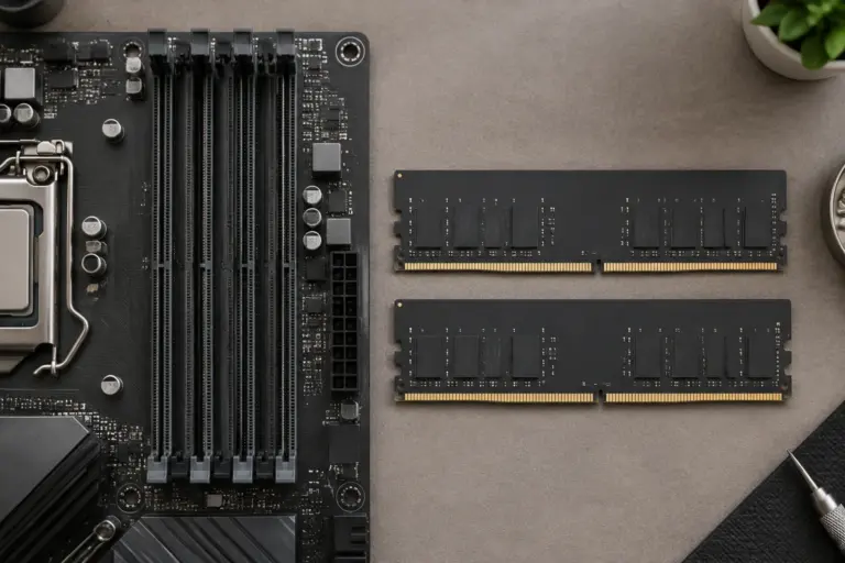
Keep Capacity by Planning for Two DDR5 Modules
Both current specifications list two DDR5 sockets and a maximum system capacity of 128GB. The GIGABYTE page explicitly lists 64GB per module. Use the current exact-board specifications when budgeting capacity, rather than an older 96GB limit carried by a review or shop description.
This comparison concerns ordinary non-ECC unbuffered consumer memory. Check the actual kit and CPU against the relevant memory support information before counting an overclocked EXPO or XMP profile as retained performance. Both boards support those profiles, but profile support is not a guarantee of a particular speed with your CPU and modules.
Four existing sticks cannot all move into two sockets. For example, four 16GB modules provide 64GB in the old board, while retaining only two of them leaves 32GB installed. If keeping 64GB is essential, evaluate a supported two-module replacement rather than assuming that moving half the kit preserves the old capacity.
Match the Case’s Front Leads, Not Just Its External Sockets
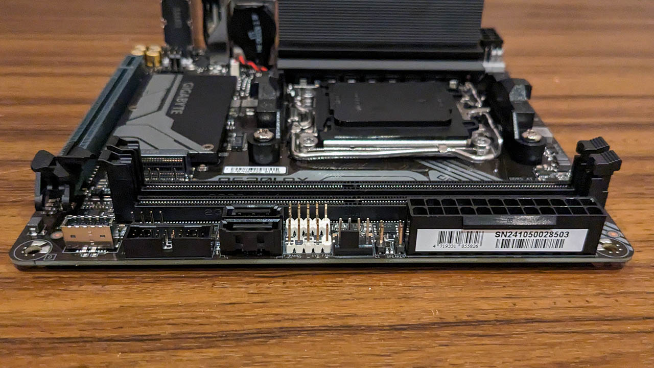
Both boards provide an internal USB 3.2 Gen1 Type-C header for a front port at up to 5Gbps. Both also provide a Gen1 header supporting two front Type-A ports and a USB 2.0 header supporting two additional ports. Match the actual leads from your case to those headers before counting every front socket as connected.
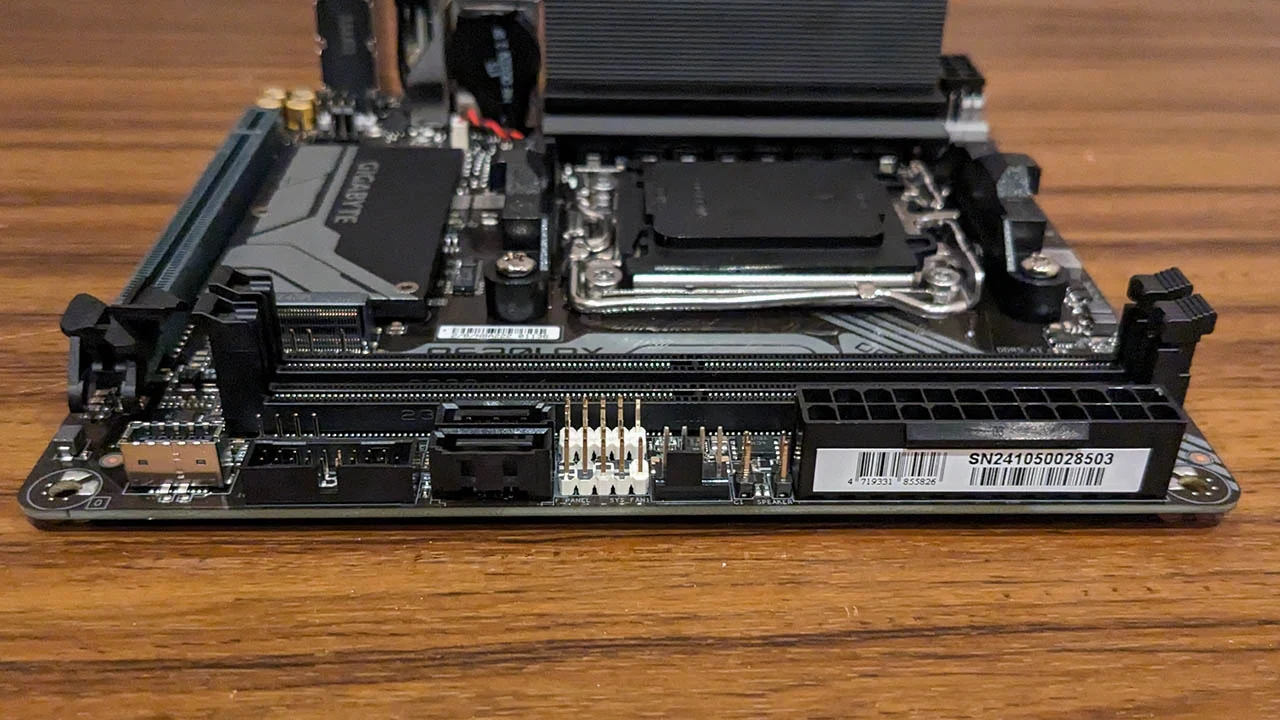
The A620I AX connector photograph shows how those case connections occupy physical space beside the main power connector and memory sockets. Check the plug orientation and room for the cable to turn in the chosen enclosure. A compatible header on the specification sheet does not establish a workable cable bend beside your particular PSU, fan or side panel.
A case with a higher-rated front Type-C port does not upgrade either board's listed front header. If your intended front-device connection requires 20Gbps, neither board's published 5Gbps front-C provision fulfills that requirement. Decide whether the slower front connection is acceptable before purchasing the board; the presence of a faster rear port is a different connection plan.
Read Rear Type-C and Its CPU Footnote Separately
Rear connectivity differs even though the front Type-C rating is the same.
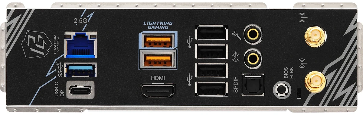
| Published connection | A620I AX rev.1.0 | B850I Lightning WiFi |
|---|---|---|
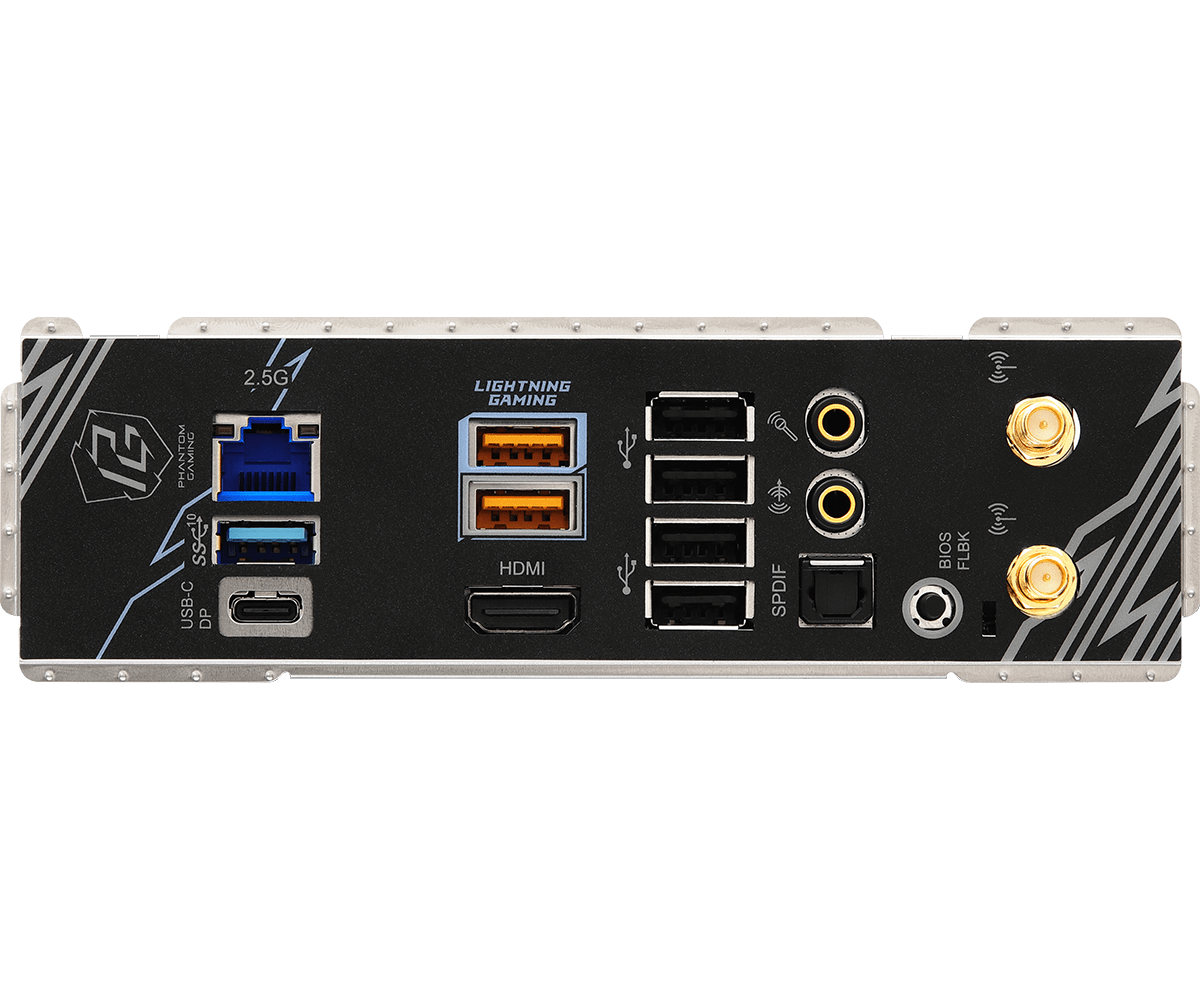
| Rear Type-C | USB 3.2 Gen1, 5Gbps | Listed as Gen2, 10Gbps, with a selected-processor maximum of 40Gbps |
| Rear 10Gbps Type-A | One | Two |
| Rear 5Gbps Type-A | One | One |
| Rear USB 2.0 | Three | Four |
| Front Type-C header | Gen1, 5Gbps | Gen1, 5Gbps |
ASRock's rear-C entry and original manual both retain the footnote that USB32_TC1 supports up to 40Gbps with selected processors. They do not identify the precise supported processor selection in those entries. Do not promise 40Gbps for every CPU, or erase the footnote by declaring the port incapable of it. If 40Gbps is the reason for choosing the B850I, obtain confirmation for your exact CPU and required device connection before buying.
The B850I also lists DisplayPort Alt Mode on that rear Type-C, with graphics support dependent on the CPU. The A620I AX separately lists DisplayPort and HDMI outputs; its Type-C data rating does not establish the same video function. Neither the Type-C shape nor this comparison establishes universal Thunderbolt support or a charging capability for your intended peripheral.
Choose Around the Whole Retained Inventory
Choose the A620I AX rev.1.0 when a confirmed CPU configuration, one onboard PCIe SSD, up to two SATA devices and the listed front connections cover the build. Choose the B850I when keeping the GPU and two onboard PCIe SSDs is central, or its documented rear connections solve a real peripheral requirement. Check that requirement against the actual CPU instead of buying solely for a headline Gen5 or conditional 40Gbps figure.
Put the two memory modules, SSD positions, GPU connection and every case lead beside the chosen board on one list. Both boards list 24-pin main power and eight-pin CPU power connections, but that does not prove the retained PSU or cooler fits the smaller case. Include the case's PSU mounting, cooler space, riser requirements if used, antennas and SSD mounting pieces in the final parts inventory. The useful smaller build is the one that preserves the components and connections you actually need.