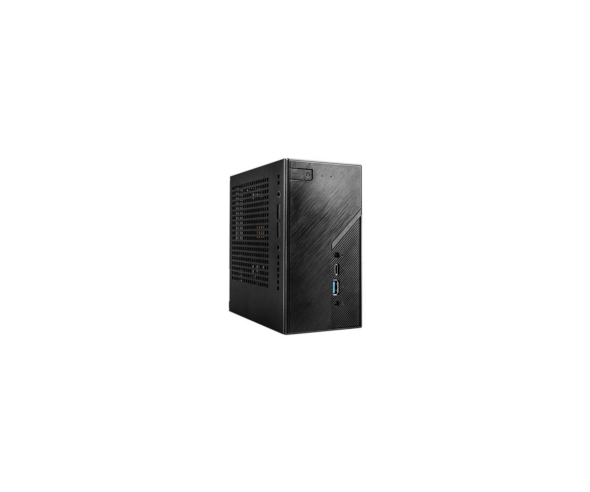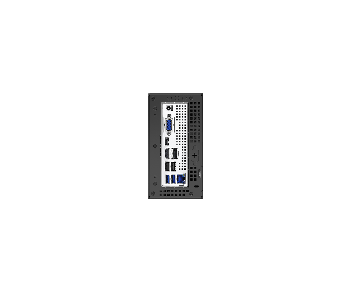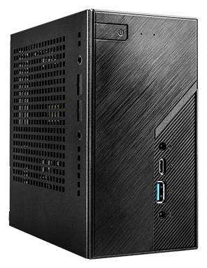
The standard DeskMini B760 can be a compact home for a supported 12th-, 13th- or 14th-generation Intel processor with integrated graphics, two DDR4 SO-DIMMs and up to four drives. Its four display paths are HDMI, DisplayPort, rear USB-C DisplayPort Alt Mode and D-Sub. Match each retained CPU, drive and monitor to its actual connection before buying the missing pieces.
This is a complete 1.92-liter barebones migration. Plan around its 65W CPU TDP limit, 47mm cooler clearance and supplied 120W/19V adapter. Desktop DIMMs, a discrete graphics card and an ATX power supply do not move into the same roles. The following allocation covers the standard B760; it does not substitute a similarly named listing for that verified specification.
Preserve the CPU, Memory and Cooling as One Compatible Set
Begin with the exact processor, its graphics capability and the BIOS installed in the unit. ASRock lists LGA1700 Core processors from the 12th through 14th generations, with a 65W maximum TDP for the barebones. That is not blanket support for every LGA1700 model. Match the retained processor to the CPU support list and required firmware before dismantling the working PC.
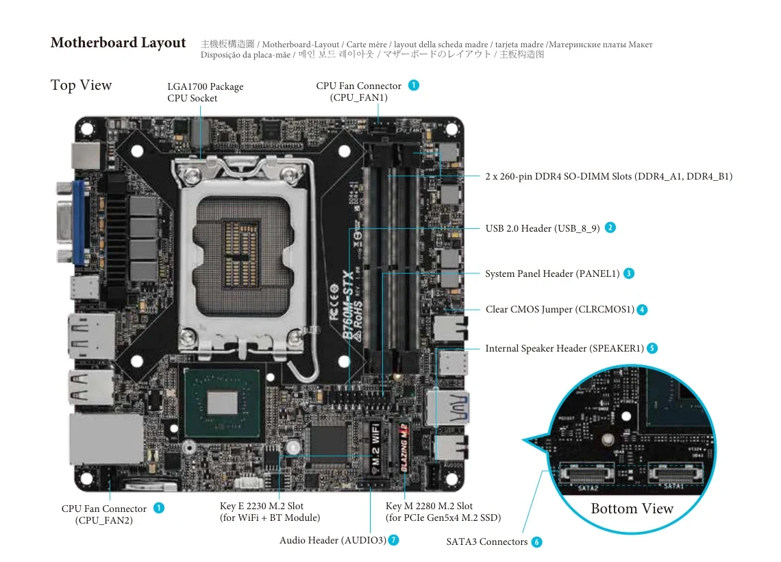
Integrated graphics is essential to this migration. The original board manual states that its graphics outputs work only with a processor that includes a GPU. The Mini-STX board has no desktop graphics-card x16 slot to replace the missing integrated graphics. Keeping a discrete card in your old parts inventory does not solve that problem inside this enclosure.
| Retained item | Keep or reselect | Condition that decides |
|---|---|---|
| LGA1700 processor | Keep a supported model with integrated graphics | Exact CPU support, BIOS and the barebones' 65W TDP boundary |
| DDR4 SO-DIMMs | Check the existing pair | Two slots, non-ECC unbuffered DDR4, up to 64GB total |
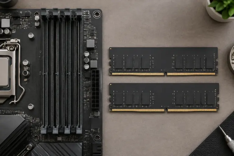
| Desktop DDR4 DIMMs | Reselect | The sockets take SO-DIMMs |
| CPU cooler | Measure the assembled cooler | Correct mounting and no more than 47mm height |
| Discrete GPU and ATX PSU | Leave outside this migration | Integrated graphics and external DC power replace those roles |
The product specification lists DDR4-3200 SO-DIMMs; the board manual also lists lower supported speeds. The installation guide calls for identical modules for a dual-channel pair. Check the actual module type and capacity rather than treating “DDR4” on the old desktop's invoice as sufficient.
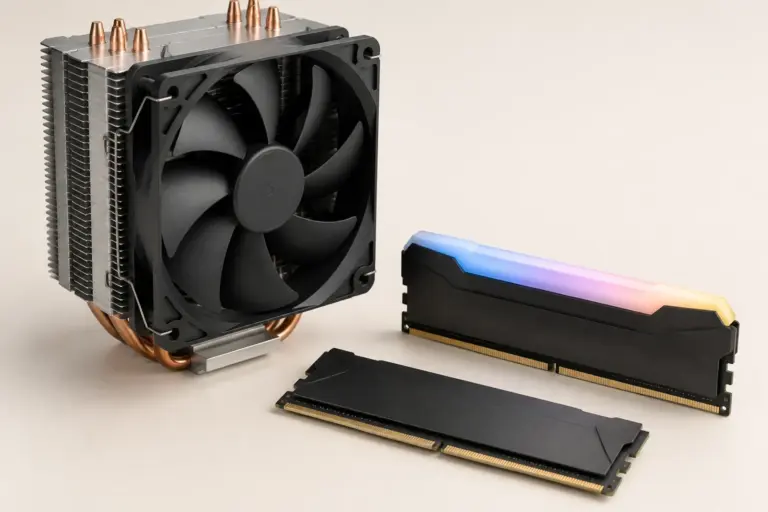
For cooling, measure the fan and heatsink together. The guide supports the Intel 65W box cooler and third-party coolers within the chassis limit, but that does not make every Intel cooler interchangeable. Confirm the actual mounting hardware, assembled height and clearance around the installed memory. A socket match without a workable 47mm assembly leaves the transplant incomplete.
Allocate the Two M.2 SSDs Before Buying Faster Replacements
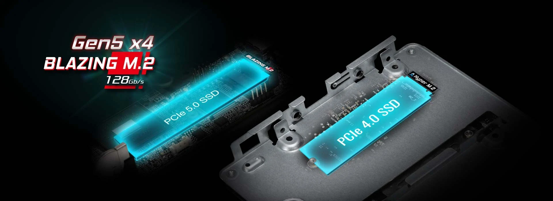
The storage map combines two PCIe M.2 positions with two cabled SATA positions. The upper M2_1 connection is Gen5 x4; M2_2 is Gen4 x4 on the underside of the board. Both storage M.2 positions are specified for 2280 modules.
| Position | Published connection | What to record for the retained drive |
|---|---|---|
| M2_1 | 2280 PCIe Gen5 x4 | Exact PCIe SSD, compatibility and heatsink clearance |
| M2_2 | 2280 PCIe Gen4 x4 | Exact PCIe SSD and access to the underside position |
| SATA tray A | 2.5-inch SATA, 7mm or 9.5mm thick | Mounting holes and one combined data/power lead |
| SATA tray B | 2.5-inch SATA, 7mm or 9.5mm thick | Motherboard-removal access and the second combined lead |
A retained SATA M.2 drive is not covered by the published PCIe storage specification merely because it has the same 2280 outline. The Key E 2230 position is for wireless hardware, not a third storage SSD. Give every retained drive a named connection instead of counting interchangeable-looking connectors.
The Gen5 label is a connection capability, not a reason by itself to replace a useful existing drive. Check that drive's actual compatibility and the clearance of any fitted heatsink. The board's slot provision does not establish room for every tall aftermarket SSD cooler in the closed chassis.
ASRock lists NVMe boot support and Intel VMD support. Those provisions do not establish that a particular existing operating-system installation will boot unchanged after the move. Record how the existing system is configured before committing the only working installation to the migration.
Plan the Second SATA Drive While the Motherboard Is Accessible
Use the B760's own installation sequence for trays A and B. The guide shows the first 2.5-inch drive secured to its mounting tray and connected with the combined SATA data-and-power cable. For the second drive, it explicitly requires removing the motherboard before installation, then turning the tray over and securing the drive with four screws. The cable assemblies finally connect to the motherboard's SATA connectors.
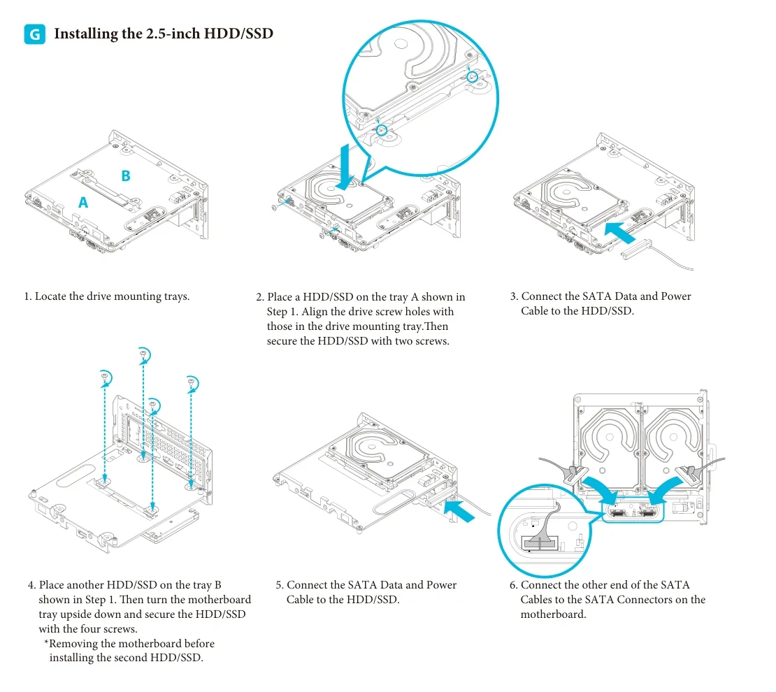
That sequence is easy to miss when comparing only drive counts. Set aside the second drive and its mounting screws before closing the tray. Confirm both combined cable assemblies are present and can follow their routes without being trapped during reassembly.
The permitted drive thicknesses are 7mm and 9.5mm. A 15mm-thick 2.5-inch disk is outside that specification. A desktop 3.5-inch HDD is also outside the internal migration: the board manual specifies 5V support for 2.5-inch drives and excludes the 12V requirement of 3.5-inch drives. Spare SATA ports or a different loose cable do not provide a published solution for that old desktop disk.
For example, two compatible PCIe 2280 SSDs and two 7mm SATA SSDs give you four drive assignments matching the listed types. Record M2_1, M2_2, tray A and tray B separately, then check the actual devices, mounting hardware and assembled cable clearances. Check that both SSDs, their heatsinks and the routed SATA leads leave the tray able to close.
Map Four Monitors to the Actual Rear Outputs
The standard B760 specification supports up to four displays simultaneously. The original manual ties the outputs to the processor's integrated graphics and describes the individual connector capabilities. Use those as separate checks for your retained monitors.
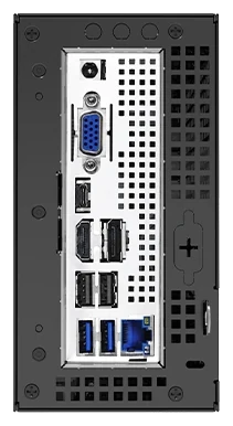
| Display path | Published capability | Migration check |
|---|---|---|
| HDMI | HDMI 2.1 TMDS-compatible, up to 4096 × 2160 at 60Hz | Monitor input, required mode and suitable cable |
| Full-size DisplayPort | DisplayPort 1.4; high-resolution modes have DSC conditions | Exact monitor, cable and supported mode |
| Rear USB-C | DisplayPort 1.4 over Alt Mode, also a 10Gbps USB connection | A display-capable connection, not just any USB-C cable |
| D-Sub | Up to 1920 × 1200 at 60Hz | Retained analog input and required resolution |
Four supported displays does not mean four 4K displays through those four connectors. The D-Sub limit is lower, and an individual DisplayPort maximum cannot be multiplied across every output. The manual's highest DisplayPort modes, including 8K at 60Hz, specify DSC compression. Establish the combined modes for your actual CPU, monitors and cables rather than adding individual maximum specifications.
Four HDMI-only monitors also do not have four directly matching sockets here. Identify the needed signal conversion and verify it for the actual source, monitor and resolution before buying adapters. An arbitrary bag of passive cables is not a verified four-screen plan.
A useful starting inventory might include one HDMI monitor, one DisplayPort monitor, one display accepting USB-C DisplayPort Alt Mode and one compatible D-Sub monitor. Assign them individually to the rear panel, record the desired resolution and refresh rate, and check those modes together with the supported integrated-graphics CPU. This preserves the real value of an existing mixed-monitor desk without promising an unverified combination.
Reserve Rear USB-C for Display and Front USB-C for Its Own Job
The two Type-C sockets serve different published roles. Front USB-C is USB 3.2 Gen2x2 at up to 20Gbps; rear USB-C is Gen2 at up to 10Gbps and carries the DisplayPort Alt Mode path in the display map. Do not move a display cable to the front simply because that socket has the higher USB data-rate number.
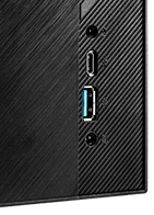
If the rear Type-C is assigned to a monitor, it is already occupied in that direct-connection plan. Allocate an external data device separately rather than counting the same bare socket twice. Front Type-A provides up to 10Gbps, while the rear has two Gen1 Type-A ports and two USB 2.0 Type-A ports.
These are USB 3.2 connections, not a published Thunderbolt or USB4 interface. The system power connection remains its 19V DC input and supplied adapter. A Type-C display connection does not establish that your monitor or dock can replace that adapter.
Buy the Complete Missing-parts List
The standard barebones package lists two SATA data-with-power cables, a 120W/19V adapter and a screw pack. A bare motherboard listing is different: its manual marks some cable and screw accessories optional. Confirm the complete case, board and system accessories in the actual purchase rather than pricing the board alone as the migration cost.
Wireless also needs an explicit package decision. The Key E socket supports a 2230 Wi-Fi/BT module and Intel CNVi; the standard system's wireless kit is optional. The B760W package lists an Intel AC-3168 kit. If buying a W listing, confirm that exact package and its documented connections; the four-output map above was checked against the standard B760 specification. An empty wireless socket is not a complete module-and-antenna installation.
Before purchase, put the supported integrated-graphics CPU, SO-DIMM pair, complete 47mm-compatible cooler, four assigned drive positions, four assigned display paths and original power accessories on one list. Add only the missing memory, cooling, mounting pieces or verified display connections. If the old desktop's discrete GPU, full-size DIMMs or 3.5-inch disks are essential assets, this smaller barebones does not preserve that same system.