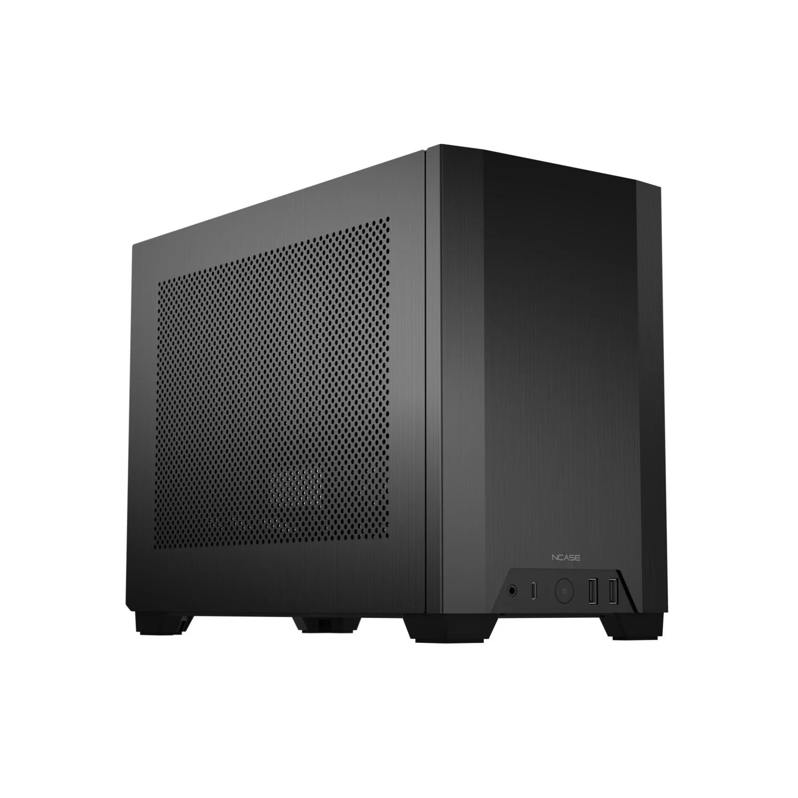
Keeping a classic NCASE M1 V6 for another upgrade means matching several shared spaces, not finding a graphics card shorter than 322 mm. Card thickness changes the permitted length, the front of a long card has a lower height allowance, and the bottom fans and original GPU support bracket have their own thickness limits. Meanwhile, the side bracket can carry cooling or drives, with combinations that exclude one another.
The useful shopping list starts with your existing case and its loose hardware. Decide which GPU outline, cooler and drive arrangement can work together, then buy only the missing parts for that arrangement.
Identify the Classic Case and the Brackets You Still Own
These dimensions concern the classic M1, with the V6 manual used for its mounting hardware. NCASE's manual index identifies M1 Classic V6.1 separately from M1EVO V1.0/V1.1 and M2. Their manuals and accessory listings are not interchangeable. The classic product page is marked discontinued and lists shipping as unavailable, so an old product page or a familiar accessory name is not evidence of new stock.
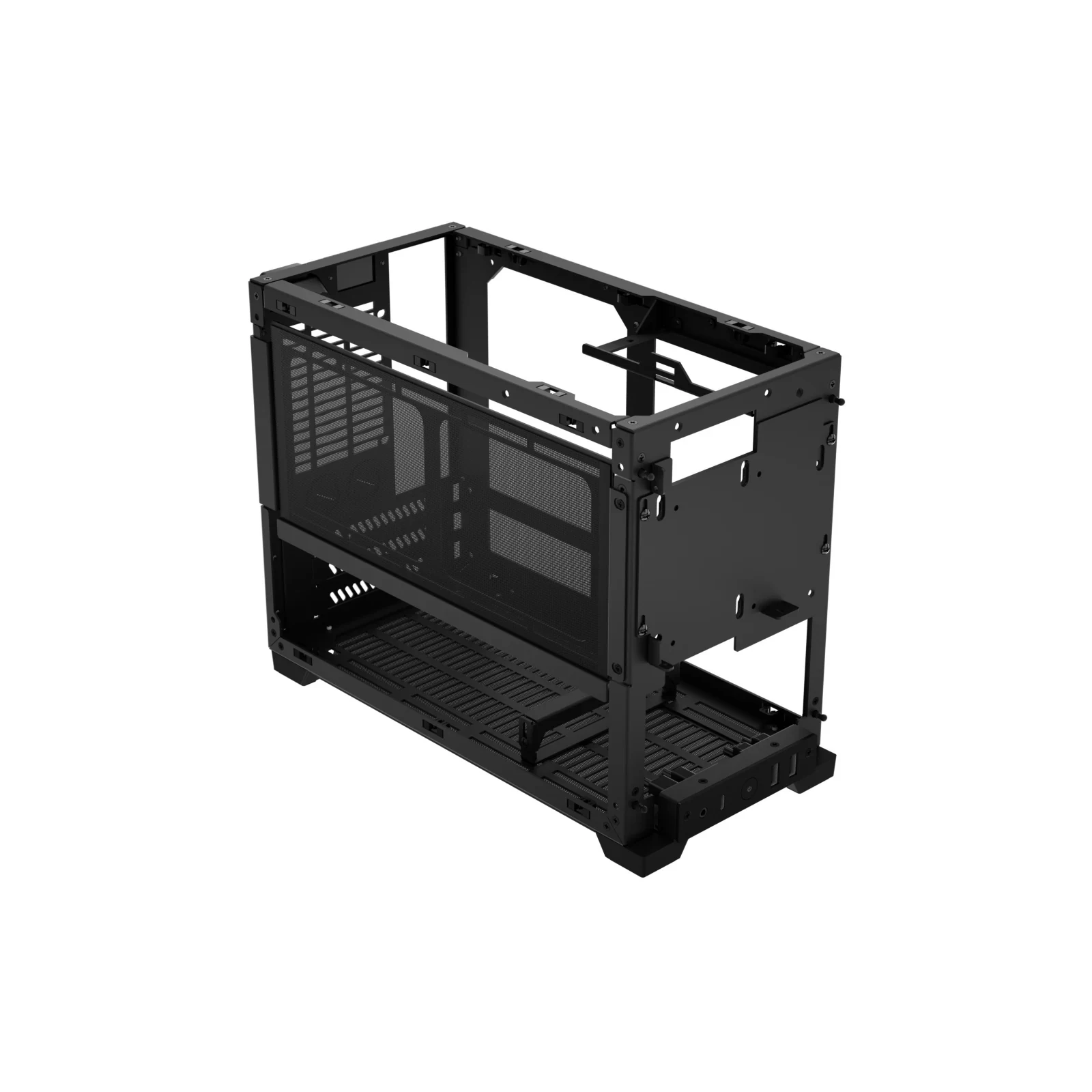
The open-chassis view is useful for taking inventory: locate the side fan bracket, front drive mounting area and bottom expansion-card space. Also find the removable HDD brackets, any SSD stacking pieces, optical-drive tray and original GPU brace in your spare-parts box. A used case may have arrived without the pieces needed for your preferred arrangement.
The classic compatibility list supports Mini-ITX and Mini-DTX motherboards, and SFX or SFX-L power supplies. Keep the exact board, PSU, cooler and cabling in the plan. A supported PSU format does not establish clearance for every cooler overhang, drive cage and cable bundle around it.
For a proposed GPU, obtain more than the headline length. You need thickness in millimeters, the height along its outline, power-connector position and the space required by the connected lead. For storage, record drive size, thickness, interface connections and the brackets actually available. That inventory prevents a purchase from depending on an accessory you do not own and cannot yet obtain.
Read GPU Length and Height as Separate Restrictions
The classic M1 has two published thickness-and-length branches.
| Card thickness | Maximum card length | Front I/O condition |
|---|---|---|
| Up to 45 mm | 322 mm | No front-I/O removal condition stated for this branch |
| Up to 60 mm | 280 mm | Front I/O retained |
| Up to 60 mm | 290 mm | Front I/O ports removed |
The 322 mm figure does not apply to every three-slot card. For example, a 300 mm card that is 58 mm thick does not pass the published length conditions simply because it is shorter than 322 mm. Nor should you interpolate a new length allowance for a thickness between the listed branches. Compare your exact part with the applicable condition, and confirm an unlisted combination before ordering.
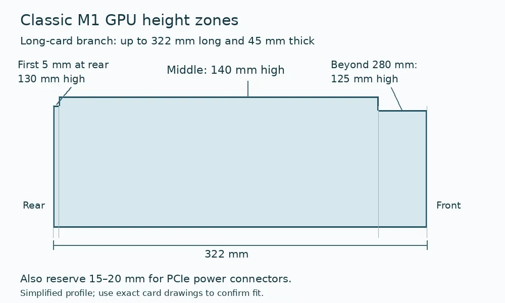
Height is a second filter. NCASE specifies 140 mm at mid-card, 130 mm for the first 5 mm at the rear corner, and 125 mm for the portion extending beyond 280 mm in length. The stepped profile shows why a single maximum-height number can hide the decisive interference. The diagram uses the long, thin-card branch; it is not permission for a 322 mm, 60 mm-thick card.
For example, imagine a 310 mm-long, 45 mm-thick card with a 130 mm-high shroud continuing all the way to its front end. It satisfies the thin-card length branch, but its portion beyond 280 mm exceeds the published 125 mm height allowance. A listing that says only “130 mm high” cannot tell you whether the nose tapers enough. Look for a dimensioned outline or ask the card manufacturer about that section.
NCASE additionally calls for 15–20 mm of room for PCIe power connectors. Include the actual plug and cable route rather than treating a bare card's published height as the occupied envelope. A recessed connector, a connector at the end and one on the upper edge create different questions; do not assume a photograph answers them.
Removing the front I/O ports is a functional tradeoff, not free clearance. If a thick card needs the 290 mm branch, decide whether losing those connections suits the machine before committing. Keep the removed parts if you want to restore the original arrangement later. The published extension to 290 mm does not remove the separate height and cable requirements.
Choose Bottom Fans and GPU Support from Actual Card Thickness
A GPU that passes the length check can still displace the fans you intended to reuse. NCASE lists two bottom 120 mm fan positions, but the permitted fan thickness depends on the installed card. The original GPU brace is another independent condition.
| GPU thickness | Published bottom-fan choice | Original GPU support bracket |
|---|---|---|
| 42 mm, the stated two-slot reference | 25 mm-thick fans | Within its 42–50 mm card range |
| Over 42 mm through 50 mm | 15 mm-thick fans | Within its 42–50 mm card range |
| Over 50 mm through 60 mm | Neither listed fan pairing is established | Outside its stated range |
The guide allows 15 mm fans with cards up to 50 mm thick. Its 25 mm fan condition is specifically the two-slot, 42 mm card class; it does not establish every thinner or unusually shaped card and brace combination. Check the actual cooler body rather than relying on a vendor's rounded “two-slot” description.
For example, a 45 mm-thick card can meet the 322 mm length branch, yet it does not meet the listed 42 mm condition for 25 mm bottom fans. Reusing a pair of standard-thickness fans is therefore a separate decision from reusing the case. Conversely, selecting a 60 mm card does not preserve the 15 mm fans or original brace merely because the card passes a shorter length branch.
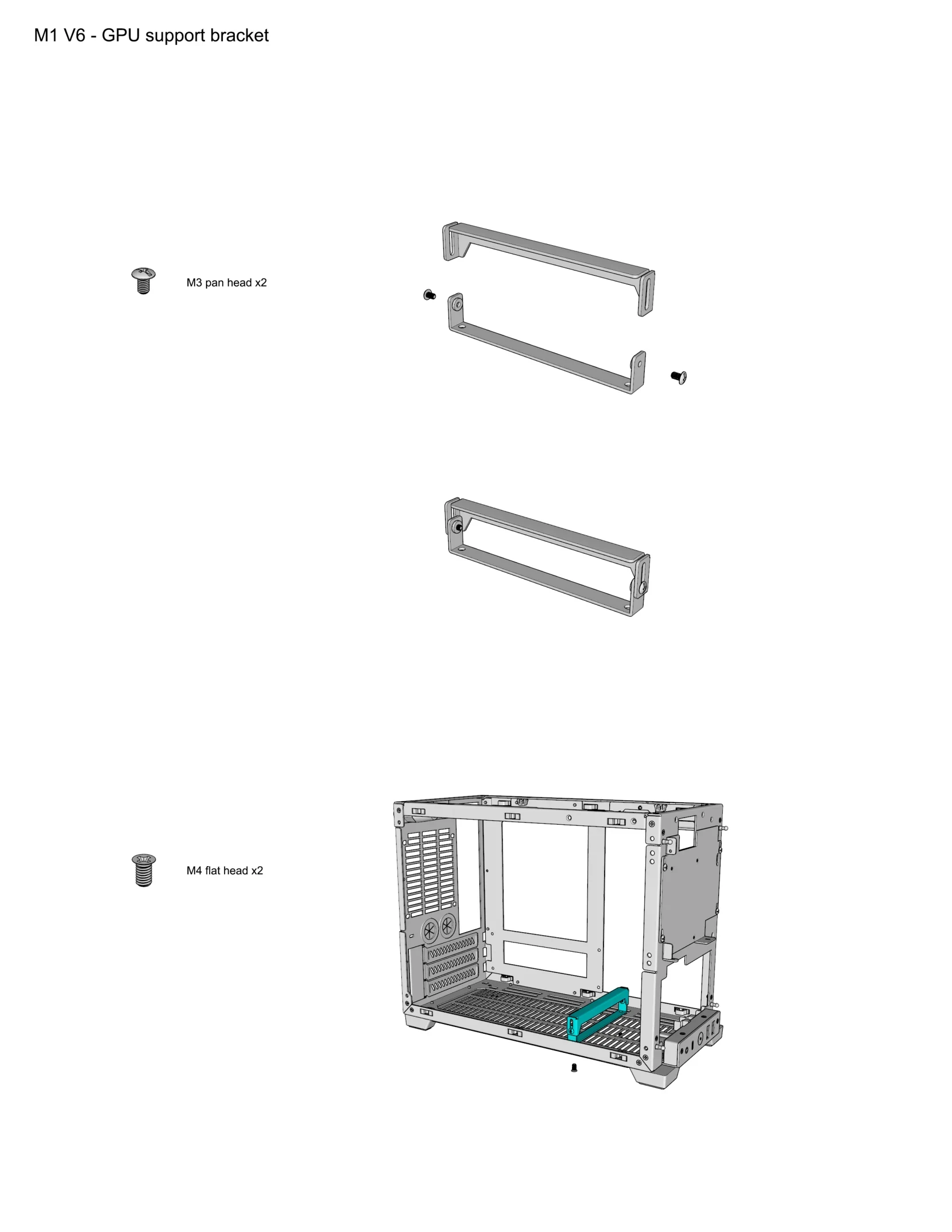
The native brace drawing shows two pieces joined with two M3 pan-head screws, then attached to the floor with two M4 flat-head screws. Check that you have the complete assembly and matching fixings before assuming it will support the new card. Its documented 42–50 mm range still applies after assembly.
For a card outside those fan or brace conditions, leave the affected item out of the confirmed reuse list. A different support solution needs its own dimensional check; do not buy a generic stand on the assumption that the occupied floor space is clear. This comparison establishes packaging choices, not a cooling-performance result for a particular GPU.
Keep the CPU Cooler, Side Bracket and Radiator in the Same Plan
The CPU cooler allowance is 130 mm with the side fan bracket installed and 135 mm without it. Removing that bracket to accommodate a taller cooler also removes the mounting structure used by the documented side cooling and drive arrangements. You cannot combine the bracket-free height allowance with a build that still needs the bracket.
There are lateral restrictions too. A heatsink must not extend more than 10 mm beyond the motherboard's top edge. A heatsink extending beyond its front edge can interfere with the HDD cage or the PSU in its default right-side position. Measure the exact cooler and socket arrangement, including its fan, rather than stopping at the cooler's height.
For example, a hypothetical 133 mm cooler falls between the two height limits. It can only be considered under the bracket-free height condition, with its remaining clearances checked. If your storage plan depends on the HDD brackets attached to the side fan bracket, that cooler and drive arrangement are not a supported combination merely because each appears somewhere in the case's specifications.
For side liquid cooling, the compatibility list supports one 240 mm radiator or up to two 120 mm radiators on the side fan bracket. NCASE recommends radiators less than 35 mm thick. That is a recommendation for radiator thickness, not a 35 mm allowance for the entire radiator-and-fan stack. Check the complete assembly and tube route against the retained board, PSU and GPU.
A 240 mm radiator or two 120 mm radiators excludes the HDD brackets attached to that fan bracket. Do not plan both and hope the drives can be squeezed behind the radiator. The documentation does not give an automatic coexistence guarantee for every single-120-mm-radiator arrangement either; that particular combination needs confirmation.
Keep Mechanical Drives Only with Their Mounting and Cooling Space
The removable HDD brackets support two 3.5-inch drives when attached to the side fan bracket, using one side 120 mm fan location. This is a specific mounting arrangement with a cooling-space cost, not a pair of spare bays independent of the fan bracket.
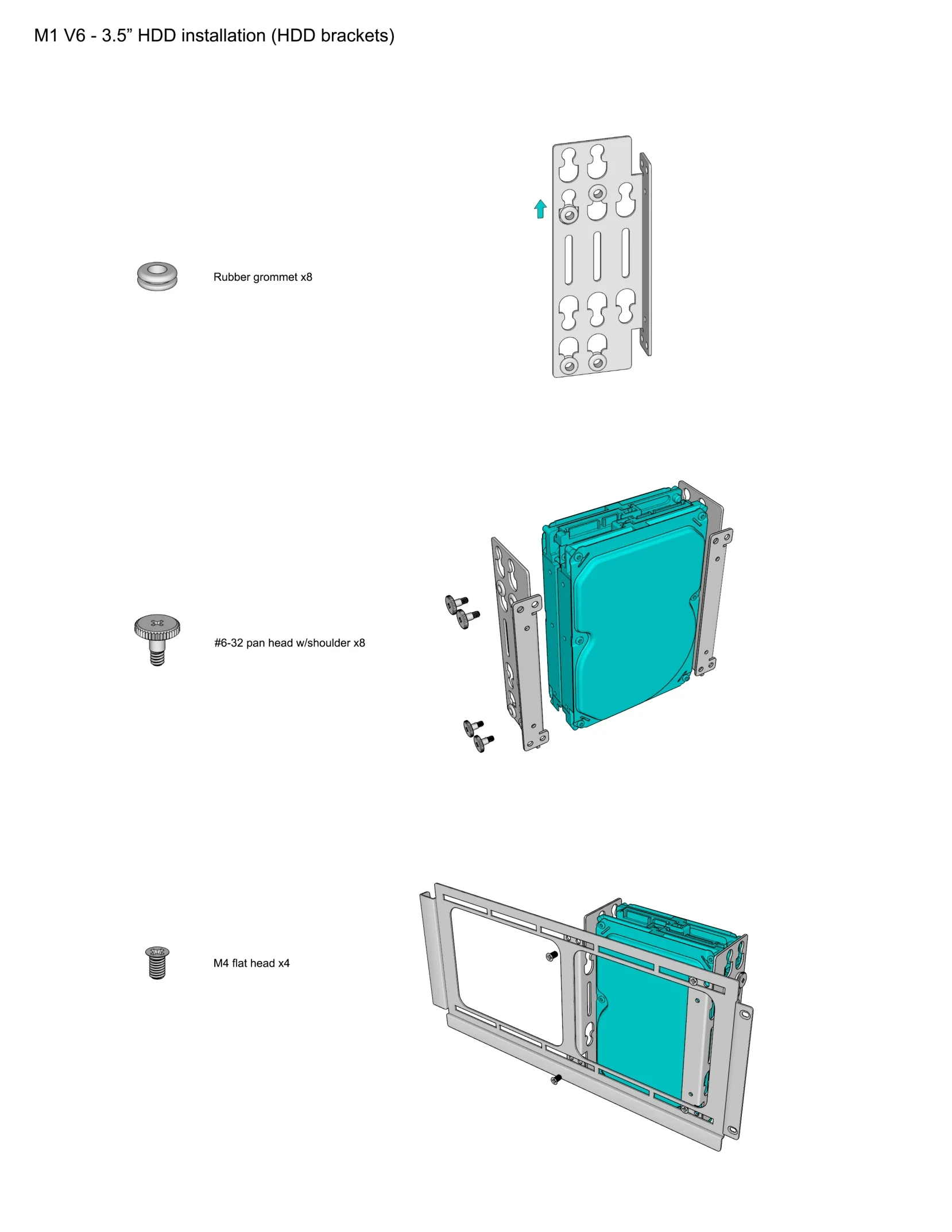
The original assembly drawing makes the retained hardware visible: eight rubber grommets, eight #6-32 pan-head shoulder screws and four M4 flat-head screws for the illustrated two-drive installation. The brackets, shoulders and grommets work as an assembly. Ordinary screws from an unrelated case do not reproduce that mounting method just because their threads seem familiar.
If you need both mechanical drives, keep the side bracket and the matching drive hardware in your confirmed inventory. Then choose CPU cooling that can coexist with them. If you also want a side 240 mm AIO, resolve the storage change before buying it: the published configuration excludes those side-mounted HDD brackets.
Check both SATA data ports and SATA power connections, with enough room to insert and route the actual plugs. A mechanically mounted drive is not a complete retained storage arrangement until its connections remain accessible alongside the selected cooler and PSU. The documentation's mounting count cannot answer that cable question for an unnamed parts combination.
Use the Front SSD Position as an Alternative, Not an Extra Total
The same removable drive brackets can instead support three 2.5-inch drives up to 15.5 mm thick. The V6 manual shows this assembly on the side fan bracket or, alternatively, at the inside-front drive mounting area. That second location replaces the ordinary single front-mounted 2.5-inch drive; it is not three drives plus that original single drive.
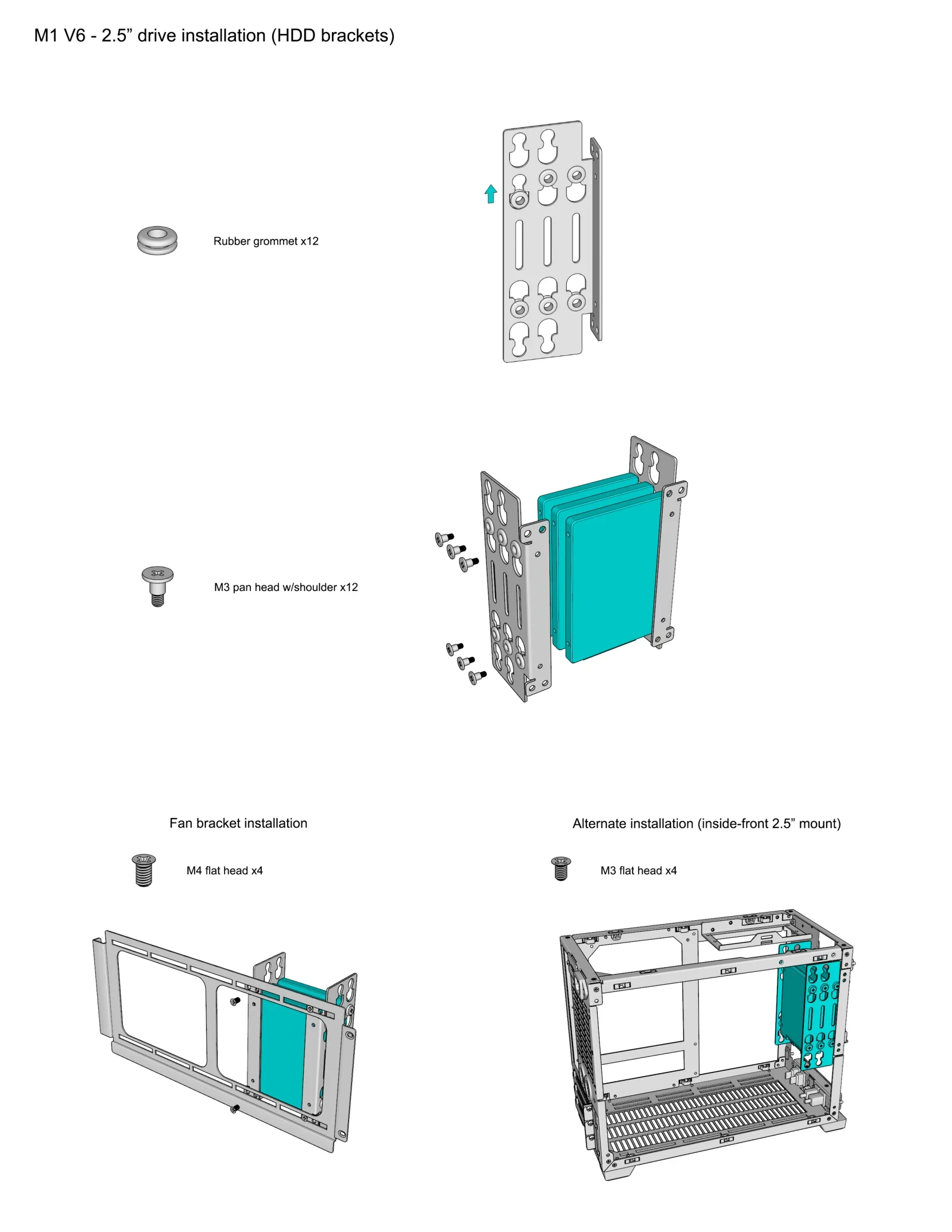
The native drawing distinguishes the hardware: twelve rubber grommets and twelve M3 pan-head shoulder screws for the three SSDs, then different mounting screws for the side or front location. For side attachment it shows four M4 flat-head screws; for the alternative front installation it shows four M3 flat-head screws. Keep those uses separate when sorting an old screw box.
| Drive arrangement | What it occupies | Main dependency to preserve |
|---|---|---|
| Two 3.5-inch HDDs on removable brackets | One side 120 mm fan location | Side fan bracket, grommets and matching HDD hardware; no side 240 or dual-120 radiator arrangement |
| Three 2.5-inch drives on those brackets | Side position or alternative inside-front position | Drives up to 15.5 mm thick and the mounting hardware for the chosen location |
| One ordinary inside-front 2.5-inch drive | Front mounting position | Single-drive fixings and clearance for its body and connectors |
| One 2.5-inch drive on the ODD tray | Optical-drive tray | Up to 14 mm drive thickness; optical-drive use is displaced |
The compatibility list puts no drive-thickness limit on the ordinary single inside-front mount, but that does not guarantee clearance against every neighboring component and cable. Check the actual drive rather than reading “any thickness” as an unlimited assembled-system allowance.
The manual also shows separate SSD stacking brackets with M3 flat-head screws. Those are different pieces from the grommet-mounted HDD brackets used for the three-SSD assembly. Identify which set you own; do not add the stacking illustration, front triple arrangement and single front mount into an invented total capacity.
An Optical Drive Needs the Matching Top Panel as Well as the Tray
The ODD tray supports slim slot-loading optical drives in 9.5 mm or 12.7 mm thicknesses. Disc access requires the optional top panel with an optical-drive slot. Having the internal tray does not make a solid top panel usable for loading discs. Confirm the actual panel and drive type when assessing a second-hand accessory bundle.
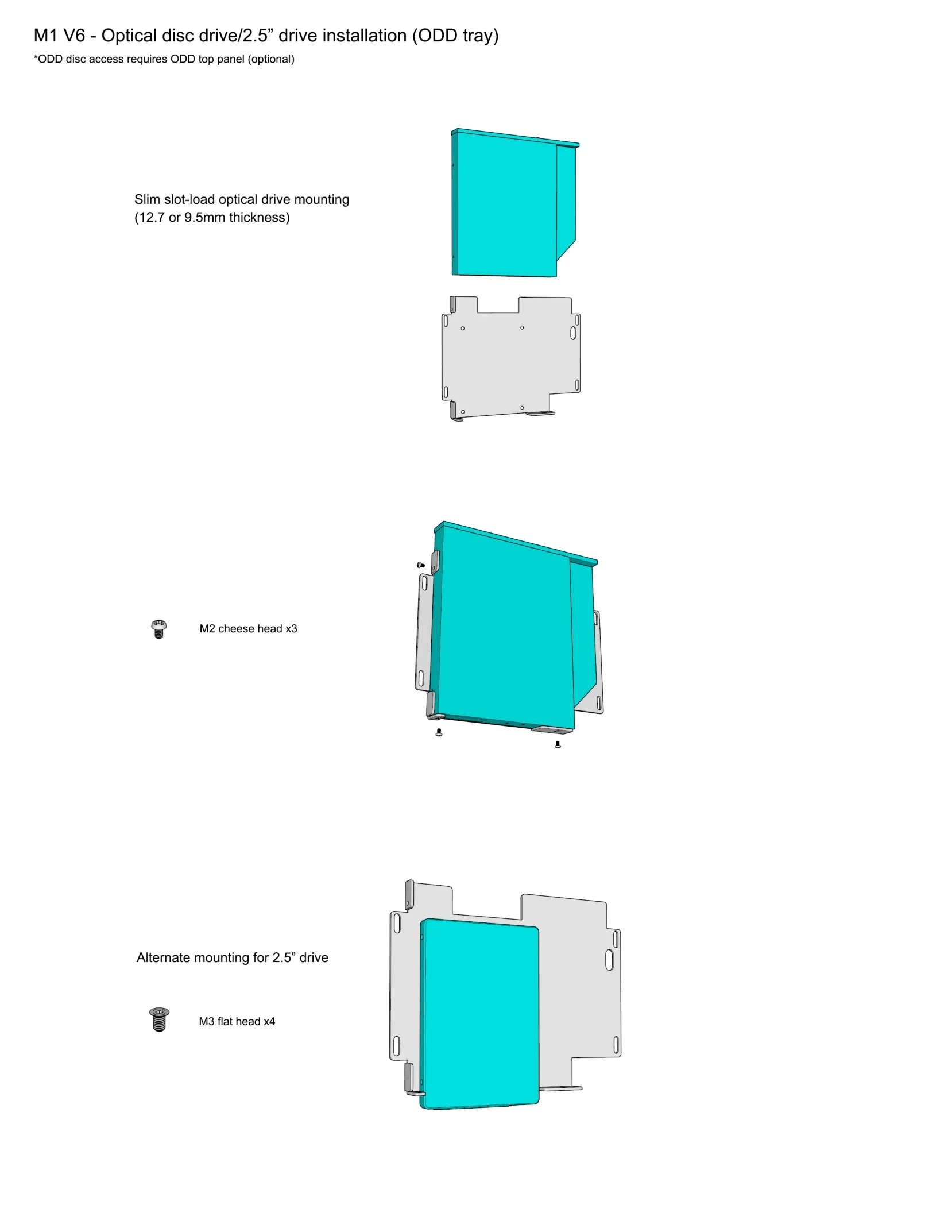
The manual illustrates three M2 cheese-head screws for the optical drive. It also shows the alternative use of that tray for a single 2.5-inch drive, using four M3 flat-head screws; the compatibility page limits that alternative drive to 14 mm thickness. These are alternative jobs for the same tray, not an optical drive with an additional SSD behind it.
Do not substitute a normal desktop optical drive or assume a tray-loading mechanism is equivalent to the specified slim slot-loading unit. If you want to retain an existing optical drive, include its actual data and power connections in the plan, together with the tray, fixings and slotted top panel. Buying only a similarly sized drive leaves the rest unresolved.
Build One Complete Keep, Change and Confirm List
Three examples show how the decisions connect; their dimensions are illustrative, not recommendations for unnamed products.
A 310 mm-long, 45 mm-thick GPU needs the long-card height profile checked, especially its portion beyond 280 mm. It also changes a plan based on 25 mm bottom fans. If the exact outline clears, compare the listed 15 mm fan route and original brace range before buying replacements. Keeping the case does not automatically keep the existing fans.
A 285 mm-long, 58 mm-thick GPU falls into the branch requiring front-I/O removal. It also falls outside the documented bottom-fan pairings and original brace range. Decide whether that loss of ports, fans and support suits the machine as a whole. A shorter card may preserve more of your current arrangement; a new case is not the only possible comparison.
An owner retaining two side-mounted mechanical drives cannot simply add a side 240 mm AIO. Choose between preserving that drive arrangement and changing the cooling, or establishing a different supported storage arrangement before ordering the radiator. Moving the drives is a component-and-hardware decision, not a label change in the parts list.
Finish by listing the exact card outline and power lead, bottom fans and support, CPU cooler and side bracket, radiator if used, every drive mount, and the matching fixings and connections. The manual's #6-32 hex-head PSU screws are marked for PSU mounting only; they are different from the #6-32 shoulder screws used with the HDD grommets. Keep screw type and purpose together rather than treating every old #6-32 screw as interchangeable.
When one of those dependencies is unresolved, hold that purchase and check the exact combination. The classic M1 remains your starting asset; the upgrade succeeds when the new parts fit its complete arrangement, with the functions and storage you actually intend to keep.