To replace a 120 mm case fan while keeping the installation practical, choose the fastening method before choosing a fan by its speed or lighting. Silent Wings Pro 4 and Silent Wings 4 offer interchangeable mounting corners. Shadow Wings 2 uses push-pins, while Pure Wings 3 and Light Wings list screw fixing. All five models below have a 25 mm-thick body and four-pin PWM motor connections, but their supplied fasteners, cables, electrical ratings and lighting connections differ.
Keeping a mounting method does not necessarily mean reusing the old fan's screws or rubber pins. The useful purchase is one complete replacement fan with the correct parts for the retained case bracket, plus a confirmed route to the existing controller or motherboard. Check the exact black 120 mm PWM model: white, high-speed, voltage-controlled and multipack versions are separate products.
Keep the Mounting Method, Then Match the Exact Model
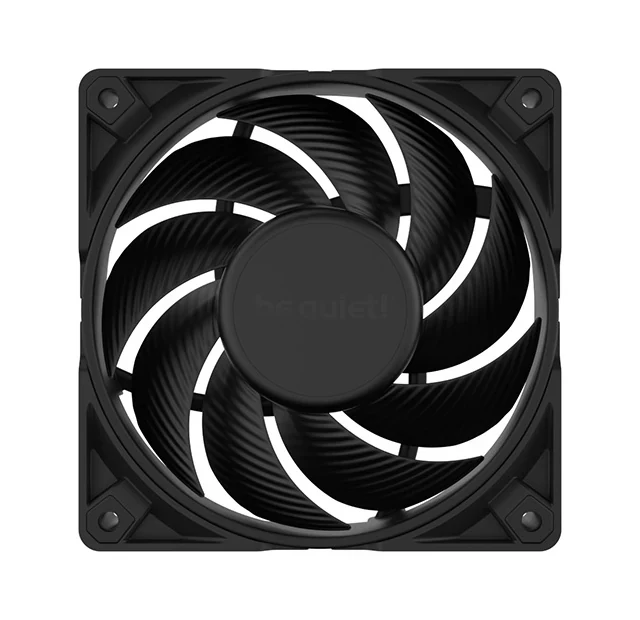
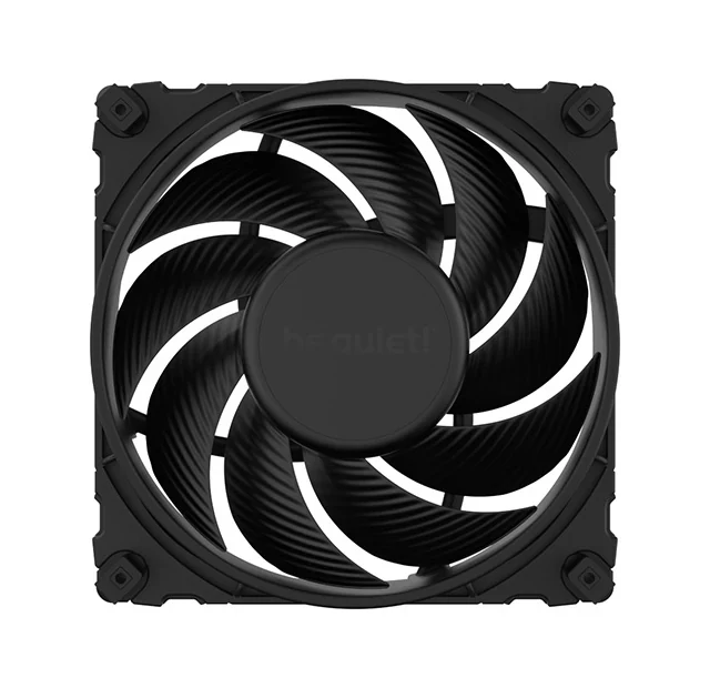
Silent Wings 4 BL093, shown here with its anti-vibration corners, illustrates why the frame matters. Its pre-installed corners support push-pin installation, and its supplied hard-plastic corners provide a screw option. A replacement with the same nominal size but a different corner arrangement may not preserve that choice.
| Exact 120 mm PWM fan | Published fixing options | Supplied fastening parts to check |
|---|---|---|
| Silent Wings Pro 4, BL098 | Push-pin and screw; three mounting-corner sets | Four screws, four push-pins, four hard-plastic washers; rubber, hard-plastic and radiator mountings |
| Silent Wings 4, BL093 | Push-pin and screw; two mounting-corner sets | Four screws, four push-pins, four hard-plastic washers; rubber and hard-plastic mountings |
| Shadow Wings 2, BL085 | Push-pin; screw fixing not listed | Four push-pins and four hard-plastic washers; screws not listed |
| Pure Wings 3, BL105 | Screw; push-pin fixing not listed | Four screws; push-pins and washers not listed |
| Light Wings, BL072 | Screw; push-pin fixing not listed | Four screws; push-pins and washers not listed |
These entries follow the individual model specifications, not a general promise about every fan in each family. They establish the intended stock mounting choices and what to look for in the box.
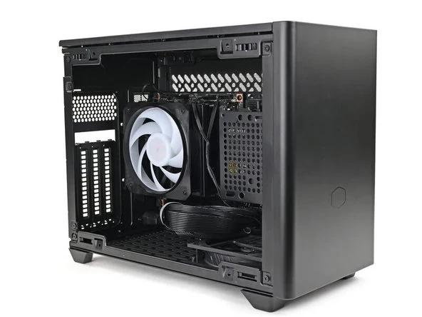
Inspect the retained case position before ordering. Is the fan attached directly to sheet metal, held in a removable carrier, secured by captive screws or clipped into a proprietary frame? Check access to both sides where the chosen fasteners need it. A screw-only carrier cannot be counted as a working push-pin installation merely because its fan opening is marked 120 mm.
Before removing the old fan, record its intended intake or exhaust role and where its cable leaves the frame. Preserve that airflow role when selecting the new orientation, using the new fan's direction markings and the case instructions. Keeping the mounting holes aligned is not enough if the cable then has to cross the blades or a connector becomes inaccessible. Make the cable-exit position part of the carrier check before choosing the fastening arrangement.
The published bodies are 120 × 25 × 120 mm. That common size does not confirm the carrier's hole shape, mounting-surface thickness, space for protruding fasteners or compatibility with a particular corner. Keep the case and bracket when those physical requirements match the new fan's intended hardware.
Change Silent Wings Corners as a Matched Set
Silent Wings Pro 4 arrives with its radiator corners installed and also supplies anti-vibration and hard-plastic mounting options. Silent Wings 4 supplies two options, with the anti-vibration corners pre-installed. If you are fitting Pro 4 as a case fan, open the complete package and select the appropriate supplied corner set rather than assuming its out-of-box configuration matches the old case installation.
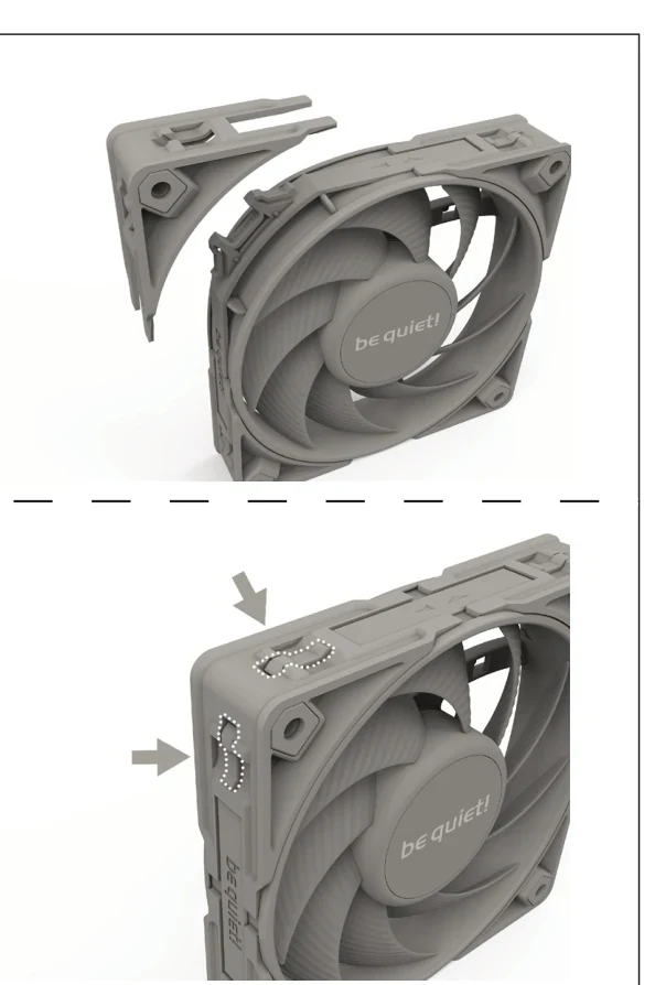
The manufacturer's corner instructions describe releasing a mounting element by pressing the latching lugs on both sides and lifting the element away. The replacement clips onto the fitting lock. The illustrated release points matter: pulling on the fan blades or forcing a corner that remains latched does not follow that procedure.
For A/B-marked parts, match the part to the corresponding frame position. The Pro 4 manual identifies the cable-exit position as Corner Type B and the remaining positions as Type A for its pictured hard-plastic fittings. Use the markings on the actual parts and the instructions for that corner set; do not assume a similar-looking corner from another fan is interchangeable.
The rubber push-pin elements also have L and S orientations. With L facing the case mounting surface, the manufacturer's guide specifies a 1 mm gap between the case and fan frame. With S facing that surface, the frame fits flush. All four rubber corners should face the same direction; the guide gives L as the default arrangement.
That gap is part of the installed arrangement. If the retained carrier has very little space around a 25 mm fan, include the selected corner position and the fastener protrusions in the fit check. Do not treat the bare fan thickness as the complete mounted envelope. Nor should a 1 mm gap be turned into a guaranteed noise reduction in your particular case.
Check that an open-box Silent Wings fan includes the corner set you intend to use, along with the appropriate pins, washers or screws. “Fan included” is not a complete description when the purchase depends on a removable mounting option that is missing.
Treat the Pro Switch as a Speed Ceiling
Silent Wings Pro 4 BL098 has a rear speed switch as well as its PWM connection. For the 120 mm model, the manufacturer's manual lists M: 1600 rpm, HS: 2500 rpm and UHS: 3000 rpm. The 140 mm values in the same manual are different, so use the column for the fan you are buying.
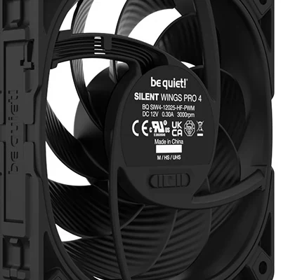
These are selectable maximum-speed settings. They are not three motherboard headers, an ARGB control or a replacement for PWM control. Check the switch position while the rear of the fan is accessible, then choose the motherboard or controller settings appropriate to the build. The rear product view helps locate the switch before the fan is installed against a bracket or panel.
Do not buy Pro 4 solely because the largest number appears to promise a better result in every case position. Its detachable corners and selectable ceiling are concrete features; cooling and noise outcomes still depend on the actual installation and operating conditions.
The current specifications list a Zero RPM mode for Pro 4 and Silent Wings 4. The other three model tables do not list that feature. Four-pin PWM alone therefore does not establish that a replacement will follow the same fan-stop behavior as the removed unit. Confirm the supported controller command and reliable restart behavior for the selected fan and board, without borrowing an unverified minimum-duty threshold from another model.
Keep a Push-Pin Route with Shadow Wings 2
Shadow Wings 2 BL085 uses a rubberized frame with anti-vibration mounts at its four edges. Its product specifications list push-pin fixing, four push-pins and four hard-plastic washers. Screw fixing and supplied screws are not listed. That makes it a candidate when the retained case position can accept its intended push-pin arrangement.
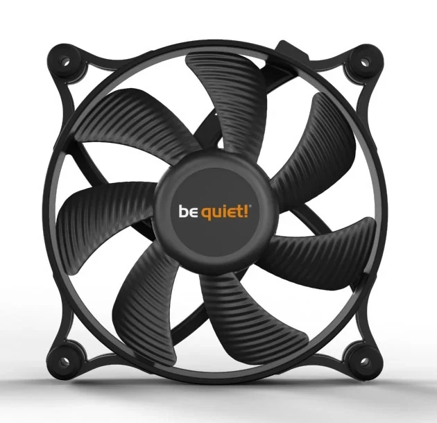
Check the actual surface and access rather than assuming that any existing rubber pin will fit. Use the matching supplied hardware, following the fan's instructions, and verify that the pins can secure the fan in the retained bracket. A thick carrier or inaccessible fastening position needs its own confirmation.
If the old fan is held by captive screws that cannot be removed from the carrier, do not count Shadow Wings 2 as a straightforward replacement. You need an explicitly compatible installation, or a fan whose intended screw arrangement matches that carrier. A bag of unrelated screws does not establish a supported screw conversion for BL085.
Keeping the push-pin approach can preserve a convenient installation method while replacing the worn fan and its matched small parts together. It does not require discarding a suitable case or buying another controller: Shadow Wings 2 still provides a four-pin PWM motor connection and a published 500 mm cable. Check that this route reaches the existing suitable header.
Use Pure Wings 3 for a Confirmed Screw Mount
Pure Wings 3 BL105 is the screw-mounted, unlit option in this comparison. Its individual product table lists four screws, no push-pins and no hard-plastic washers. The frame has the same published 25 mm thickness as the other four fans, but its mounting parts do not reproduce their interchangeable or push-pin arrangements.
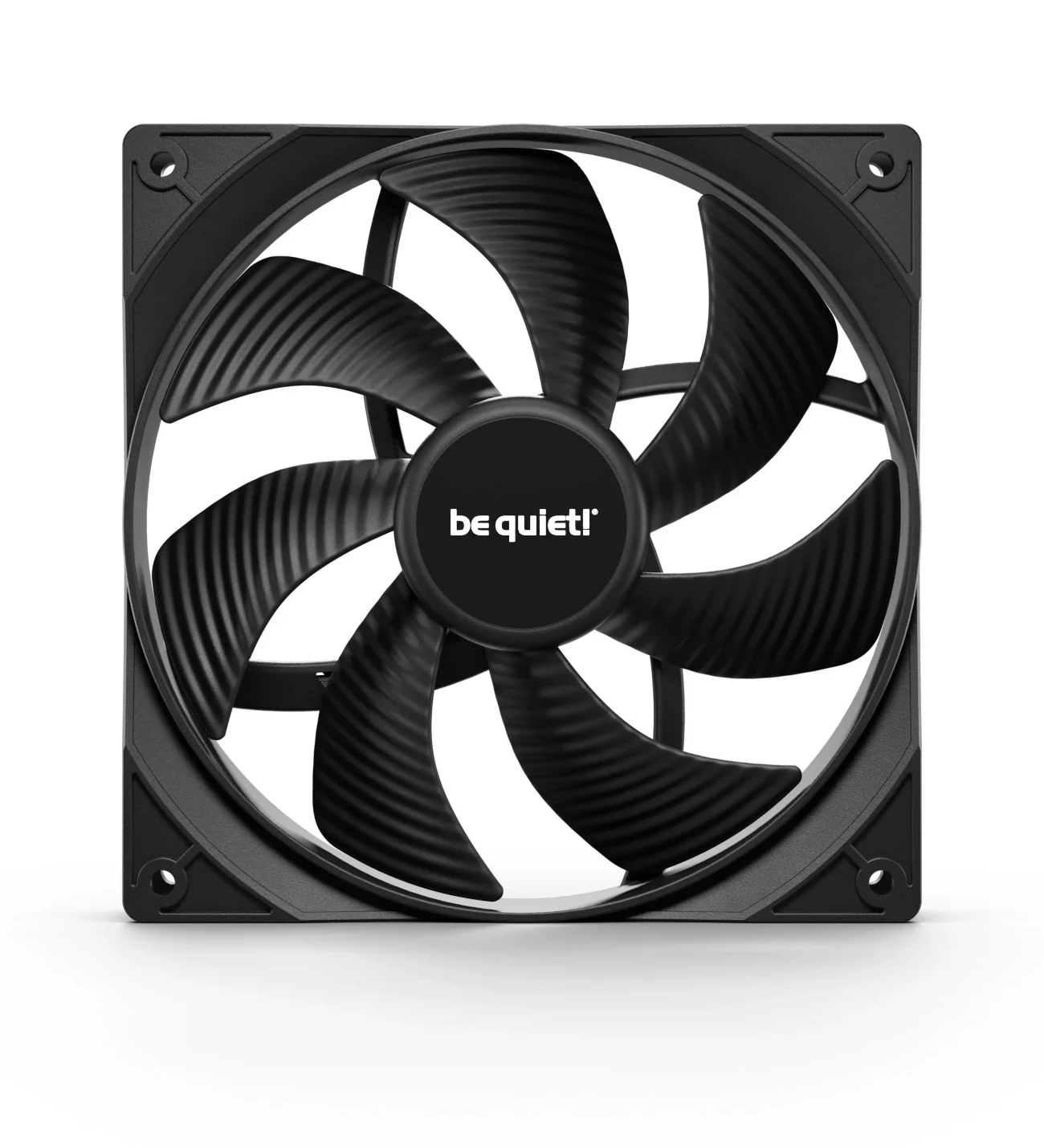
Choose it for investigation when the retained case position already accepts the appropriate screw installation and there is no need to preserve a push-pin-only method. Check the screw requirements for the actual carrier. The existence of old screws is not proof that they have the right thread, engagement or length for the replacement.
Its PWM cable is listed at 460 mm, compared with 500 mm for the other four models. Measure the intended routing path around brackets and behind panels, not just the straight-line distance from fan to header. A fan may fit the opening while its lead fails to reach the retained connection without being stretched or trapped.
For example, if your planned routed path is approximately 480 mm, the published 460 mm lead does not establish a workable direct connection. A correctly matched PWM extension may solve that particular gap after its length and route are checked. It is a smaller, more relevant purchase decision than replacing the case or adding an unnecessary powered hub.
Give Light Wings a Separate ARGB Path
Light Wings BL072 combines screw fixing with a four-pin PWM motor connection and a separate 5V three-pin ARGB lighting connection. Its published cable length is 500 mm, and the individual package lists four screws. It does not supply the push-pin mounting options of the Silent Wings or Shadow Wings models above.
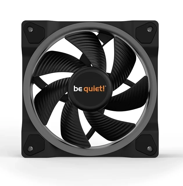
Before retaining an existing lighting controller, confirm that it supports this specified 5V ARGB connection. A three-pin lighting lead is not the same thing as a three-pin voltage-controlled fan-motor lead. Likewise, a 12V RGB connection is not the specified 5V ARGB path. Keep motor control and lighting control as separate checks.
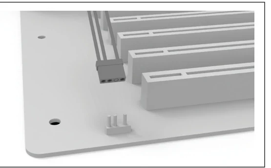
The model table lists daisy-chain compatibility, but that entry is not a complete motor-power wiring plan. Keep its four-pin motor lead and 5V ARGB lighting lead on their respective compatible paths. Follow the manufacturer's instructions for the actual lighting arrangement and check the applicable limits before linking devices. For a single-pack installation, the family manual shows the ARGB lead connecting directly to the motherboard's 5V ARGB connection, with the system switched off.
Check the actual package type before adding a hub to the expected contents. The manufacturer's fan guide and family manual identify the ARGB hub with Light Wings triple packs. This comparison uses the individual BL072 fan, whose accessory table does not list that hub. Do not transfer the triple-pack contents to the single-fan order.
Light Wings is also a different product from an AIO's proprietary Light Wings LX fan-and-extension arrangement. Keep the exact BL072 connector requirements in view when replacing a case fan. If the retained motherboard or controller has no confirmed compatible ARGB path, establish a suitable solution before choosing it for synchronized lighting, or choose an unlit alternative that meets the mounting task.
Compare the Cable Route and Both Electrical Ratings
All five motor connections are four-pin PWM and have a published 12V rated motor voltage. That shared interface does not make their electrical loads identical. The manufacturer's specifications distinguish input current from a separately labeled safety current; keep both figures when checking the retained header or controller.
| Exact fan | Cable length | Motor input current | Published motor safety current | Zero RPM mode listed |
|---|---|---|---|---|
| Silent Wings Pro 4 BL098 | 500 mm | 0.30 A | 0.30 A | Yes |
| Silent Wings 4 BL093 | 500 mm | 0.12 A | 0.12 A | Yes |
| Shadow Wings 2 BL085 | 500 mm | 0.10 A | 0.12 A | No feature listed |
| Pure Wings 3 BL105 | 460 mm | 0.10 A | 0.20 A | No feature listed |
| Light Wings BL072 | 500 mm | 0.07 A | 0.38 A | No feature listed |
These are published model ratings. In particular, Light Wings' lower input-current entry is not a reason to ignore its higher stated safety-current figure. Compare the required load against the board or controller's documented per-header and shared limits, including any required startup allowance. Do not assume that the fan's published “safety current” label is a complete measurement of every startup condition.
For a retained splitter or controller, account for every motor already connected, rather than checking only the new fan. If the relevant limits or requirements are missing, obtain them before treating the connection as approved. This is a compatibility check for the retained equipment, not a reason to add a new hub automatically.
Light Wings separately lists 0.60 A rated LED current. Keep that lighting requirement on the 5V ARGB side of the plan. Do not combine it with the 12V motor rating as though both belonged to one interchangeable header. Check the lighting controller or motherboard's own connection and chain limits.
Route either lead clear of the blades and moving parts, and leave access to the intended connectors. A workable extension is only an addition when the retained connection is otherwise suitable; extra cable length does not correct the wrong voltage, an incompatible controller or an unresolved electrical load.
Order the Complete Fan Around What You Can Keep
Make the final selection in this order: retain a compatible case position and carrier, choose its supported fastening approach, confirm the cable route and motor control, then confirm lighting only if the selected fan needs it. Buy the exact fan with the mounting parts used by that choice.
For a hypothetical screw-only carrier, Pure Wings 3 or Light Wings can remain candidates if their actual screw installation and clearances match. The Silent Wings models also offer screw options with the correct corners. Shadow Wings 2 remains unresolved for that carrier because its specification does not establish the same fixing route. Lighting availability and the shorter Pure Wings cable then separate the remaining choices.
For a case position intended for push-pin installation, investigate the matched Silent Wings or Shadow Wings mounting arrangement instead. If you choose a Silent Wings rubber corner set, decide on L or S consistently across all corners and confirm the resulting clearance before installation. Keep the suitable case and control hardware while replacing the fan and its appropriate fastening parts.
The package check is concrete: the correct corners where applicable, all four intended fasteners and the specified washers where used. Add a PWM extension or compatible ARGB control solution only when the retained build demonstrably needs it. The result should be one complete replacement fan that preserves a workable installation, rather than a collection of adapters intended to compensate for an unconfirmed mounting choice.