An existing AM5 desktop can move into the HDPLEX H5 without replacing its CPU, memory or storage, but keeping the motherboard and keeping the old power supply are separate decisions. The H5 accepts ATX, microATX and mini-ITX boards; its current compatibility table reserves ordinary internal ATX, SFX and FlexATX power supplies for mini-ITX. A full-size board therefore changes the power plan, even when its integrated graphics make a separate graphics card unnecessary.
Treat the move as a complete kit: the correct AM5 mounting parts, the eight-heatpipe CPU assembly, a motherboard-compatible power arrangement, drive racks and the original case cables. Start with the parts you want to retain, then check whether they can occupy the H5 together. Buying the enclosure first and resolving those relationships afterward can turn a case change into an unintended platform replacement.
Identify the Complete Cooling Kit
The H5 is more than a low enclosure with vent slots. Its side panels form part of the CPU heatsink. Heat travels from the processor into a copper base, through eight copper heatpipes and into grooves in the side panel. A finned aluminum top plate clamps the pipes at the CPU end; separate plates secure them at the chassis end. The enclosure and the cooling hardware need to be considered together.
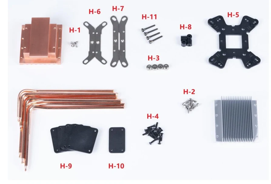
The photograph shows the original general CPU installation kit, including parts for different sockets. It is useful for recognizing a complete assembly, but the older AMD mounting pieces pictured there do not establish that a used set includes the separate AM5 four-screw pack.
For a secondhand H5, ask for clear photographs of the copper block, all eight pipes, the finned top, the side clamps and the socket hardware. The V4 manual identifies four full-width heatpipe installation plates, H-9, plus one half-width H-10. The product page's shorter package list mentions four installation plates; use the manual's identified pieces when checking the actual kit rather than assuming that four unspecified plates settle the inventory.
Also check for both multipurpose drive racks, the universal PSU rack, AC extension, power-entry plates, motherboard studs and the internal USB cables. These small pieces determine whether the old parts can be mounted and connected. A bare enclosure with intact exterior panels can still be missing the hardware that makes this particular migration practical.
Use the AM5 Mounting Instructions
The AM5 procedure is on page 9 of the V4 installation guide. Remove the two original front heatsink mounting brackets, but leave the motherboard's original AM5 backplate untouched. Install the four dedicated AM5 screws, then place the copper base with the AMD mounting rails over them. The screw-pack and installed-post photographs below identify this arrangement.
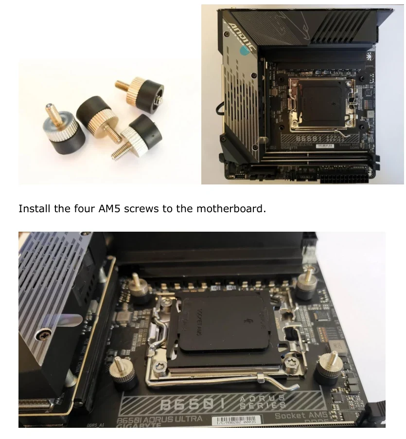
Do not apply the earlier generic AMD procedure indiscriminately. That section describes installing HDPLEX's own bottom rack behind the board; the later AM5 instructions explicitly retain the motherboard's bottom rack. The distinction changes which pieces you remove and which hardware must be present before dismantling a working PC.
For an older H5 package sold as “AMD compatible,” ask specifically whether the AM5 four-screw pack is included. The answer cannot be inferred from an AM4 label, the presence of AMD rails or a bag containing four visually similar screws. Obtain the correct parts rather than adapting unrelated cooler hardware.
Socket support is also only the first fit check. HDPLEX describes a long copper contact base and offers to confirm motherboard compatibility. Send the exact board model and photographs showing the socket area, nearby capacitors, memory and heatsink covers. A board can use AM5 while presenting a different physical route between the CPU and the side panel.
Check the Entire Heatpipe Route
The connection photograph makes the important relationship visible: the pipes leave the copper block, bend across the board and enter the side-panel grooves. The CPU base, pipe bends and side clamps need their intended positions simultaneously. Space directly above the socket alone does not establish that the complete assembly clears tall memory or motherboard armor.
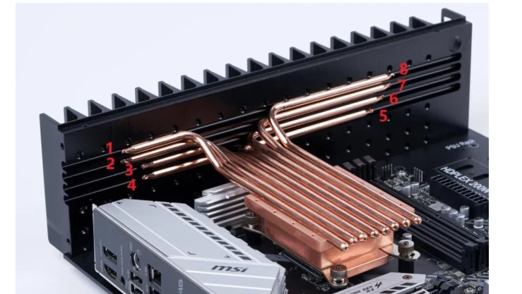
Follow the numbered eight-pipe arrangement in the manual. It calls for a thin layer of thermal paste in the copper-base and side-panel grooves, then secures the pipes with the side plates and finned CPU top. The side plates are not square; their orientation matters when matching the mounting holes. Where a full-width plate would crowd the rear of the case, the manual provides the half-width H-10.
A missing half plate is therefore more than a cosmetic omission. Depending on the board's position and pipe arrangement, it may be the piece needed to secure that end properly. Check the actual assembly before assuming a missing clamp can be ignored or replaced by tightening another one harder.
HDPLEX lists AM5 support and a 125W TDP figure in its CPU compatibility description. That manufacturer specification is not a guarantee of a particular AM5 processor's sustained temperature in your room, workload or cabinet. Integrated graphics remove the need for a separate GPU, but do not by themselves establish the CPU package's cooling demand. Confirm the specific processor and board combination, then check temperatures during the work you actually intend to run.
Decide Which Matters More: the Board or Old Power Supply
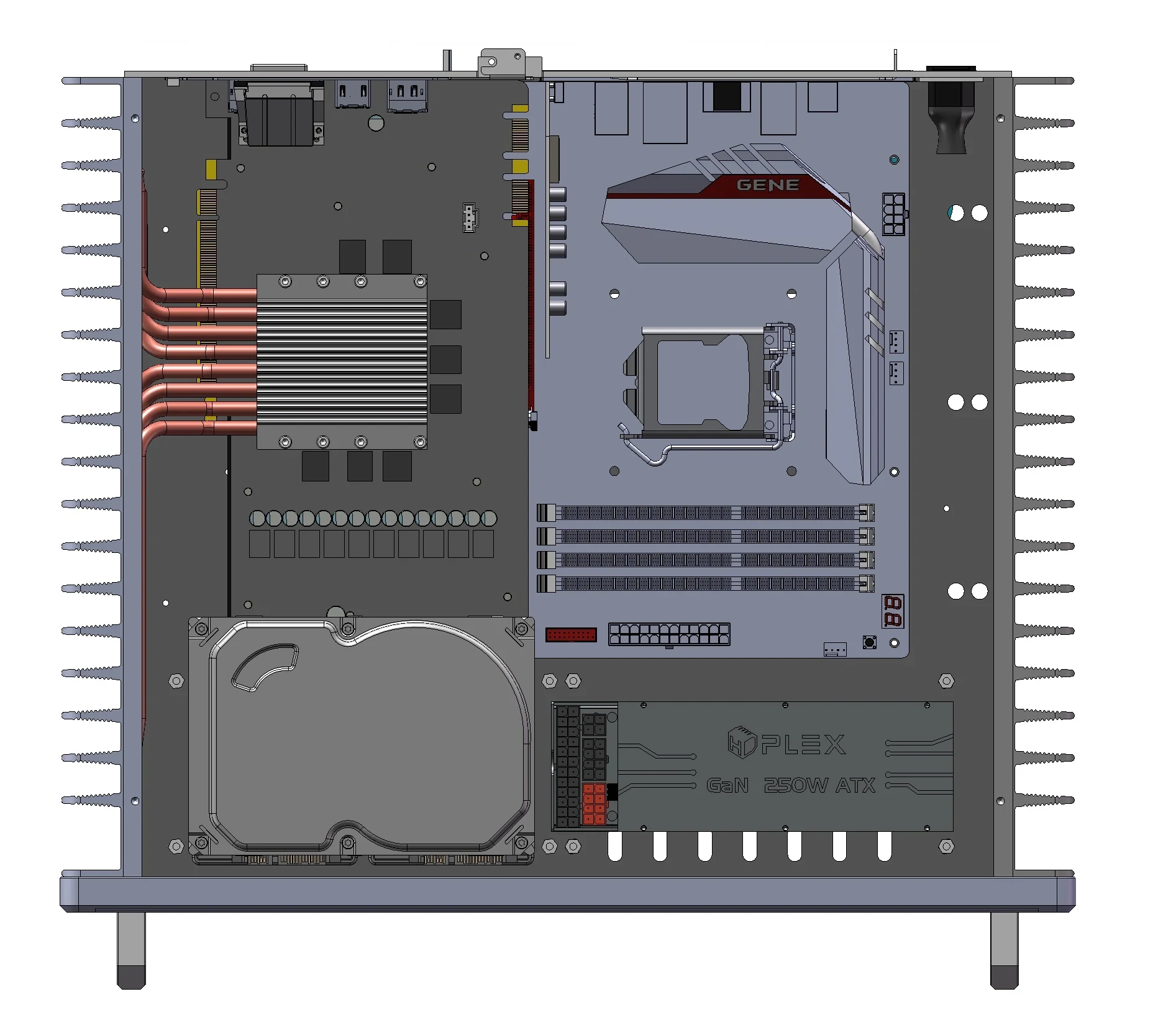
The manufacturer's layout illustration below shows the compact 250W GaN supply occupying the floor beside the motherboard area. It explains the space-saving arrangement; the illustrated board and other hardware are not a verified AM5 migration configuration.
Use the current compatibility table as the default purchasing rule:
| Board you retain | Ordinary ATX, SFX or FlexATX PSU inside | Supported compact power routes to investigate |
|---|---|---|
| ATX | Listed as unsupported | HDPLEX GaN or DC-ATX arrangements |
| microATX | Listed as unsupported | HDPLEX GaN or DC-ATX arrangements |
| mini-ITX | Listed as supported | Standard PSU with original rack, or a supported compact arrangement |
The manual also mentions standard supplies with a “narrow width” ATX or microATX board. It does not give a universal qualifying width. Treat that as a combination requiring confirmation from HDPLEX, not permission to buy an H5 on the assumption that any ATX board and old SFX supply will coexist. Provide both exact models and your drive plan when asking.
If keeping the ATX motherboard is the priority, budget for the supported power arrangement rather than treating the existing PSU as automatically reusable. A DC-ATX converter needs the appropriate external adapter and original input hardware; it is not, by itself, a complete mains-powered supply. The internally housed GaN route has a different mounting and cable inventory.
For the 250W GaN AIO ATX supply, the H5 manual specifies back mounting on the right-hand floor using the PSU's supplied M2.5 screws. Its optional front mounting plate is not used. The relevant floor position may carry an older “400W AC-DC” marking; identify the actual case revision and fastening arrangement instead of choosing hardware from the printed wattage label alone.
If a mini-ITX board allows the old standard PSU to remain, use the original universal rack and the included 45cm internal AC extension with its right-angle IEC connector. Check the PSU's actual length, cable exits and the extension's route alongside the drive racks. Retain the PSU's matching output cables; a suitable case bracket does not make another modular supply's cables interchangeable.
Retaining a conventional supply also retains its cooling behavior. A case with passive CPU cooling does not turn a fan-equipped PSU into a fanless one. Decide whether the benefit you want is removing the CPU fan, reducing the whole machine's noise or achieving a fully passive configuration before buying replacement parts.
Plan Drives and Power Together
The rack illustration shows a 3.5-inch drive on top and two 2.5-inch drives underneath. This is a mounting relationship, not a promise that every motherboard and PSU arrangement accepts every possible populated rack position. Two racks are included, but their available locations depend on the rest of the build.
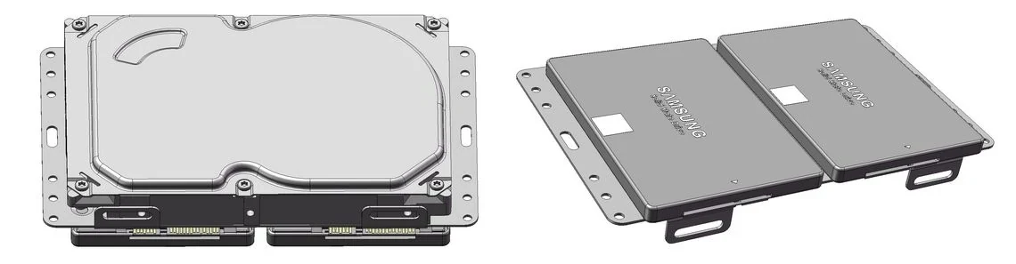
The manual supplies separate screws for 3.5-inch and 2.5-inch drives, plus 10mm and 25mm rack studs. It also describes stacking a second rack and using a side position with a mini-ITX motherboard. Those options are useful precisely because board size and occupied floor area change where storage can go.
One illustrated arrangement raises a rack on two joined 25mm studs above the older 400W NanoATX combination. That 50mm example belongs to that stated power setup. Do not transfer it directly to a 250W GaN build and assume the same drives, cables and lid clearance have been approved together.
For your retained disks, make a short physical plan:
- Assign each drive to a particular rack and position.
- Leave room for both SATA data and power plugs, including the cable bends beyond the rack.
- Check that the rack and wiring avoid the CPU heatpipe route and the chosen PSU.
- Count reachable motherboard SATA ports and suitable power connectors before closing the case.
The manual notes that the 2.5-inch drive connectors project slightly beyond the rack for cable access. Keep that extra space in the layout; measuring only the metal tray can hide the very collision that prevents the side panel or lid from fitting.
For example, retaining an ATX board, one mechanical disk and two SATA SSDs is a different decision from retaining a mini-ITX board and several mechanical disks. The first may favor a compact supply and one populated rack; the second may use additional rack positions but consume the space needed by a retained standard PSU. These are layouts to confirm, not universal combinations established by the drive count alone.
Keeping a mechanical hard drive also keeps a source of mechanical sound. Passive CPU cooling can remove a fan without removing disk activity noise. If the existing disk is important for capacity, retain it deliberately rather than expecting the enclosure change to make it inaudible.
Match the Side Ports to the Motherboard
The actual side-panel photograph shows two USB Type-A ports and one Type-C port between the heatsink fins. The product specification describes two USB 3.0 ports and a USB 3.1 Type-C connection with a Type-C onboard connector. Check the supplied internal cable ends against the headers on your exact motherboard. Having USB-C somewhere on the rear panel does not establish that the internal case cable has a matching destination.
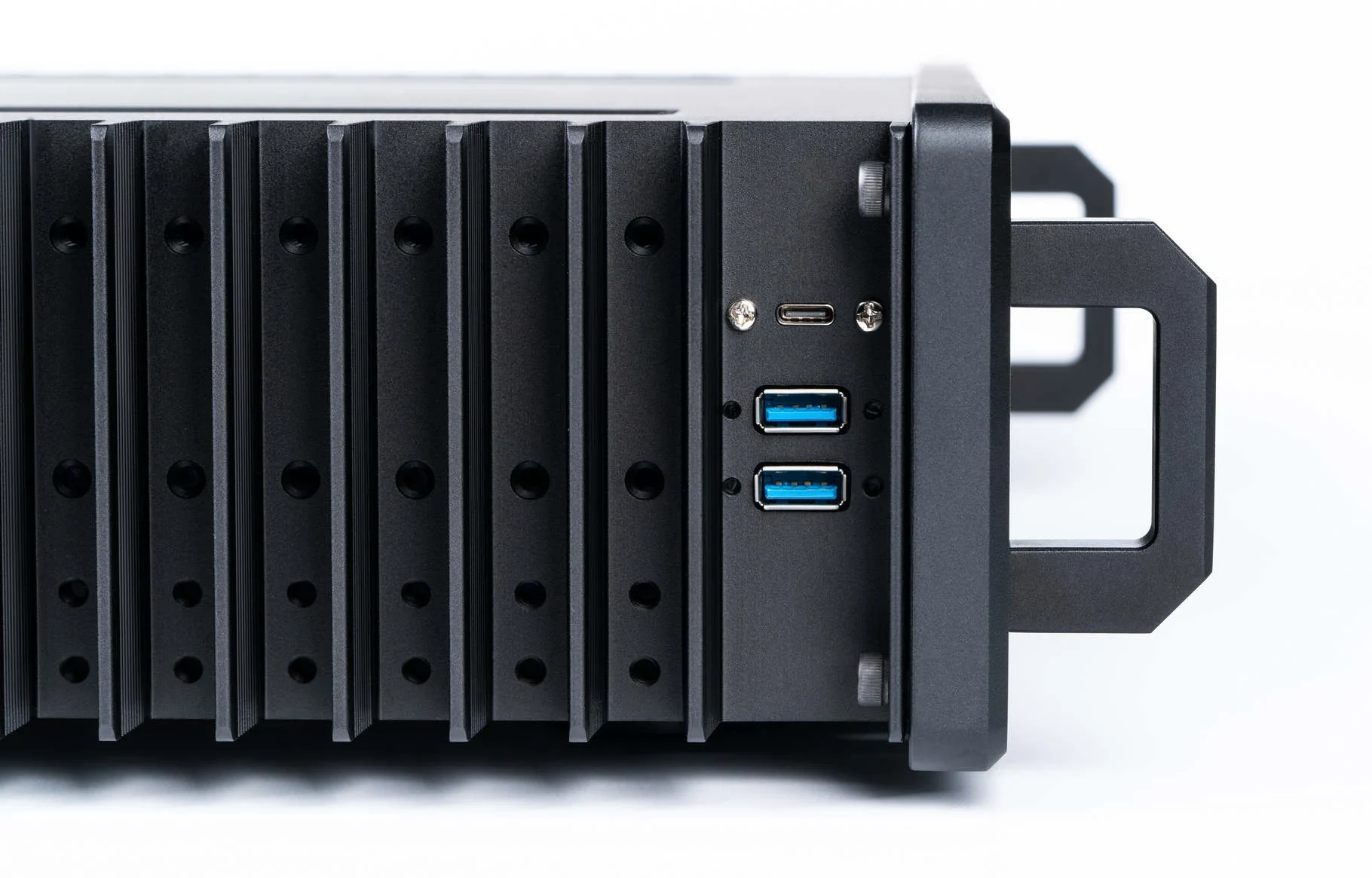
Lay out these cables while the board and racks are still accessible. A connector that technically matches the board can still be difficult to reach once a drive tray occupies the space above it. Keep the plugs and wiring clear of the CPU assembly rather than resolving a blocked header after the heatpipes have been clamped down.
Connect the power-button lead according to the motherboard's front-panel header instructions. Keep the original cable and button hardware with the case during the move. The H5's ports and switch are part of its side-panel assembly, so their cables belong in the migration inventory alongside the larger CPU and storage parts.
The package includes two rear plates: a low-profile arrangement and one for horizontal dual full-height cards. An iGPU build does not need the separately sold passive GPU heatsink or PCIe riser simply because those accessories appear in H5 examples. Choose the rear plate for the actual retained hardware and power entry.
Check the Finished Enclosure’s Footprint
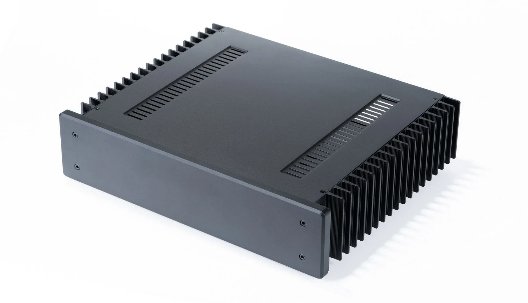
The manufacturer's front drawing distinguishes the 102.5mm face height from the 109.75mm overall height including the feet. Overall width is 430mm. The side drawing shows 388.5mm depth with the handle, so a shelf chosen only from the shorter body dimension may leave the handle projecting or the rear connections crowded.
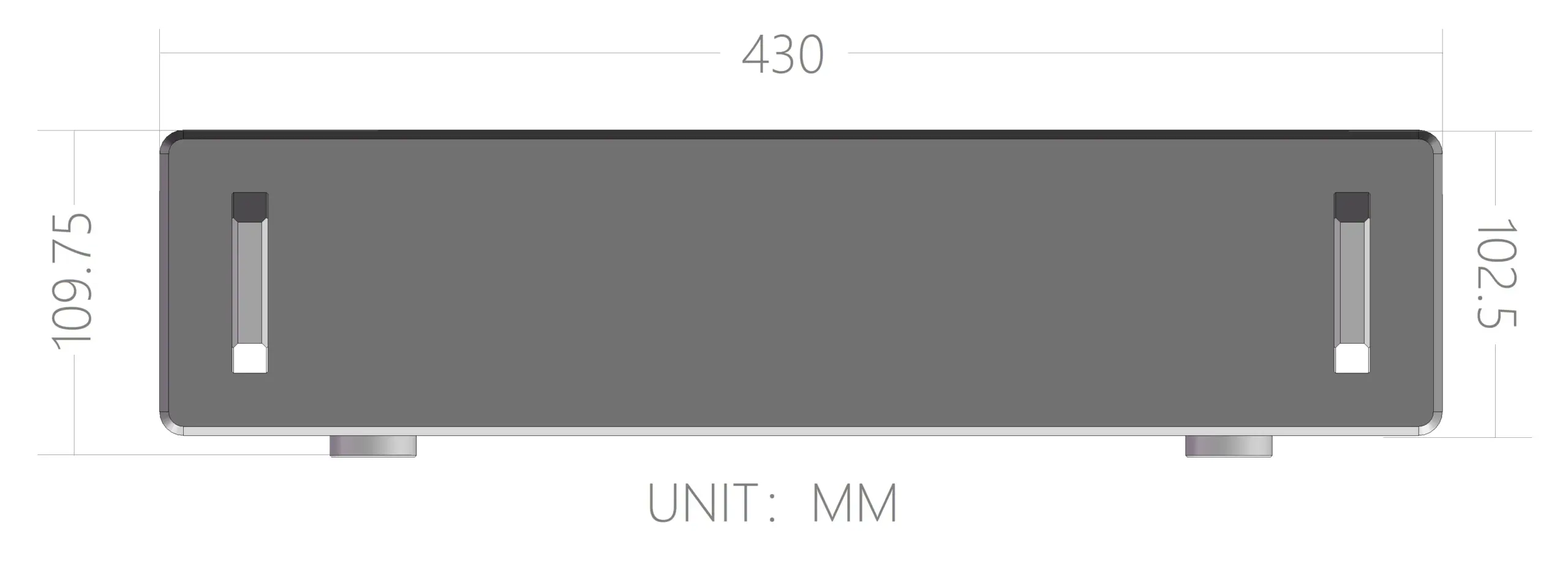
The internal drawing's 88mm height is an interior measurement, not the enclosure's external height. None of these dimensions alone establishes cooling clearance in a closed cabinet. Check where the side fins and top openings will sit, and leave them exposed rather than fitting the H5 tightly between surrounding objects.
Also include the space needed for your display cable, network connection and power lead. An iGPU migration normally sends the display connection through the motherboard's rear outputs; verify that the existing display arrangement remains usable at the new location before dismantling the old case. The useful result is a working desktop in its intended position, not merely components that fit within the enclosure.
Make the Move Without Losing Track of the Kit
Use the two retention priorities to settle the purchase first. If you want to keep a known-good ATX board and DDR5, confirm its CPU heatsink clearance and the compact PSU arrangement, then place the retained drives around that combination. If you want to keep a mini-ITX board and an old SFX PSU, confirm the original PSU rack, AC extension, cable exits and drive positions together. Neither route needs a new motherboard merely for the sake of using the H5.
Before disassembly, back up important files, record the working hardware and photograph the existing drive and front-panel connections. Verify the H5's complete cooling kit and AM5-specific screws while the old PC is still usable. Stop at a missing mounting part or unconfirmed board/PSU combination rather than leaving the machine dismantled while trying to improvise a replacement.
Next, arrange the board, PSU and drive racks in the intended positions and check the cable paths. Follow the manual's AM5 mounting procedure, assemble the complete heatpipe connection and fit storage and case cables around it. Install the appropriate power-entry plate before attaching the rear plate, as the manual specifies. Use the original finished power leads and mounting hardware for the chosen supply.
Finally, test the PC and the heatsink assembly before closing the top, then check the finished machine under its intended workload. The manual explicitly calls for thorough testing before the top plate is fitted. If the lid or panels resist installation, resolve the alignment; do not use the screws to force a collision between the case, pipes and retained parts.
The sensible H5 purchase is the combination that preserves the parts you value while completing the cooling, power and storage arrangement. If keeping both a full-size board and the old standard PSU remains essential but their exact combination cannot be confirmed, retaining the old enclosure is a valid outcome. The case change should solve a defined problem without creating an unsupported parts combination.