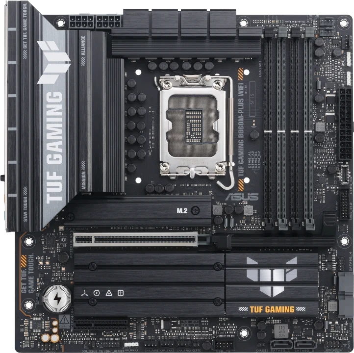
For an Intel Core Ultra Series 2, LGA1851 rebuild, the ASUS TUF GAMING B860M-PLUS WIFI and MSI B860M GAMING PLUS WIFI preserve different parts of a larger PC. TUF provides a main Gen 5 x16 GPU connection, a second Gen 4 x4 card connection and three M.2 positions that each support an x4 link. MSI adds two electrically x1 card positions and onboard Thunderbolt 4, but its third SSD sits behind the board and uses a Gen 4 x2 connection.
The choice depends on the complete retained arrangement: GPU thickness, small cards, SSD lengths, case wiring and external devices. MSI's four long card connectors are not four x16 electrical connections, and its Thunderbolt port does not promise 40Gbps with every USB-C device. TUF's rear 20Gbps Type-C port supports video, but an internal Thunderbolt header is not an onboard Thunderbolt port.
1. Start with the CPU, Four Memory Modules and Case
Both boards support Core Ultra processors, Series 2, in LGA1851. Check the exact processor and required BIOS in the chosen model's CPU support information. For motherboard display outputs, keep the processor's graphics capabilities in the plan; MSI explicitly limits its onboard video outputs to CPUs featuring integrated graphics, while ASUS also makes graphics specifications CPU-dependent.
Both have four DDR5 memory sockets and a published maximum of 256GB, including support for non-ECC, unbuffered memory and CUDIMMs. That preserves a possible four-module configuration, subject to the exact memory type, part numbers, CPU and compatibility list. It does not establish that four retained modules will run at the headline overclocked memory rate.
MSI's specification separates one- and two-module-per-channel speed conditions. Use the matching configuration rather than carrying its highest advertised number into a four-module build. For either board, record the actual kit and supported configuration before deciding whether the existing RAM can stay.
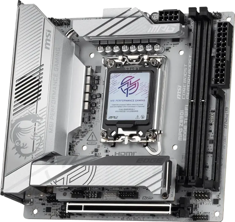
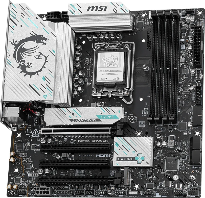
Both boards are approximately 244mm square mATX designs. Check the case's actual mounting positions, expansion brackets and clearance around the retained cooler and graphics card. MSI's whole-board view shows four closely spaced long card connectors; the PCB footprint alone cannot establish which remain accessible after the GPU is fitted.
2. Assign the GPU, x4 Card and Smaller Cards Separately
The main GPU position on either board is CPU-connected and supports up to PCIe 5.0 x16. Each also provides a chipset-connected PCIe 4.0 x4 card position. MSI has two additional chipset-connected connectors, each limited to PCIe 4.0 x1, despite their long physical shape.
| Card position | TUF B860M-Plus WiFi | MSI B860M Gaming Plus WiFi |
|---|---|---|
| Main GPU | CPU Gen 5 x16 | PCI_E1: CPU Gen 5 x16 |
| Second x4 connection | Chipset Gen 4 x4 | PCI_E4: chipset Gen 4 x4 |
| Additional x1 positions | No additional positions listed | PCI_E2 and PCI_E3: chipset Gen 4 x1 each |
For example, a retained GPU plus one card requiring a Gen 4 x4 connection has an electrical candidate on either board. On MSI, assign that card to PCI_E4, not to a middle connector merely because the card fits its length. If the card requires a CPU-connected secondary slot, neither board's documented lower x4 connection satisfies that requirement.
A GPU plus two suitable x1 cards creates a different comparison. MSI lists the necessary extra electrical positions; TUF's two-position inventory does not provide three separate card locations. Yet MSI's inventory is only the starting point. Compare the GPU cooler's occupied brackets, each small card's height and bracket, and the case floor or PSU shroud against the actual layout.
The middle and bottom positions can be obstructed even while unused lanes remain. Do that physical assignment before ordering the board, and check each card's own compatibility requirements. Separate chipset connections also share upstream resources; adding their nominal link rates does not produce a guaranteed simultaneous transfer rate.
3. Put Each SSD in a Named Position
Both boards list three PCIe M.2 storage positions and four SATA 6Gb/s ports. Their drive-length options and third-drive links differ. Keep the actual retained SSD model, length and role beside each slot name.
| M.2 position | TUF | MSI Gaming Plus |
|---|---|---|
| First | M.2_1: CPU Gen 5 x4; 2280 | M2_1: CPU Gen 5 x4; 2242, 2260, 2280 |
| Second | M.2_2: chipset Gen 4 x4; 2242, 2260, 2280 | M2_2: chipset Gen 4 x4; 2260, 2280 |
| Third | M.2_3: chipset Gen 4 x4; 2280 | M2_3: chipset Gen 4 x2; 2280; rear |
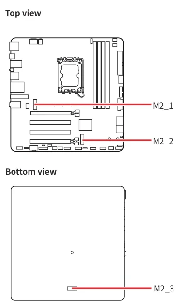
For three suitable 2280 NVMe drives, both inventories provide length-compatible positions. TUF keeps an x4 connection at all three. MSI's third drive uses x2, so do not describe it as an equivalent third Gen 4 x4 path. Its original position drawing also places M2_3 on the back of the board.
For a retained 2242 drive, TUF's listed location is M.2_2, while MSI's is M2_1. That short drive therefore takes MSI's CPU-connected Gen 5-capable position, leaving the other two drives on the chipset connections. The drive's supported link still determines what it can negotiate; putting it in a Gen 5 connector does not turn it into a Gen 5 SSD.
A 2260 drive has two listed choices on MSI, M2_1 or M2_2, but only M.2_2 on TUF. All three drive assignments must work together. The wireless Key E socket is not a fourth storage position, and an M.2 SATA drive cannot simply inherit these PCIe-slot assignments.
4. Check MSI’s Back-side SSD and Individual Heatsinks
MSI's front/back drawing makes the underside drive an assembly consideration. Check the actual M2_3 position against the case tray, mounting standoffs and drive or heatsink height before fastening the board down. A CPU-backplate cutout does not automatically provide access to the SSD's location.
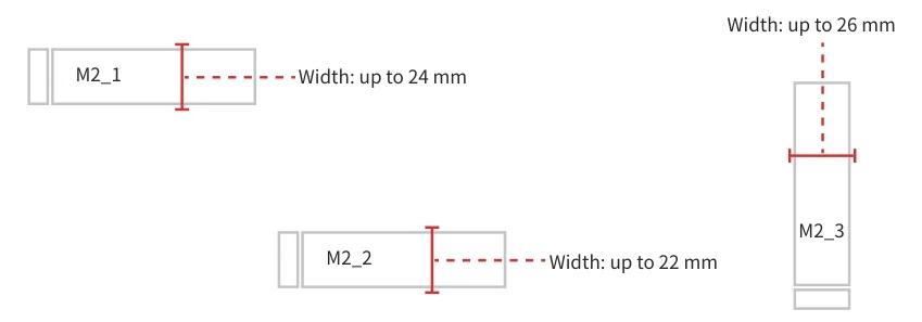
The original MSI manual gives these maximum heatsink widths: 24mm at M2_1, 22mm at M2_2 and 26mm at M2_3. The vertically drawn M2_3 outline has a 26mm width limit. These are width limits, not permission to use a heatsink of any height. MSI also says to consider the installed PCIe card's height when checking M.2 installation space.
For an SSD with its own heatsink, MSI instructs users to remove the M.2 plate or rubber cube as applicable and not reinstall the motherboard-supplied heatsink over it. Its rear-drive installation uses the supplied standoff and screw. Account for those pieces and access to them before the tray obstructs the work.
Do not apply MSI's numerical limits to TUF. Check the actual SSD, selected cooling arrangement and neighboring cards on the chosen board. A supported 2280 length proves neither heatsink fit nor clearance beneath the retained GPU.
5. Give MSI’s Two Rear Type-C Ports Different Jobs
MSI's rear hardware view shows one Thunderbolt 4 Type-C port and a separate USB 5Gbps Type-C port. The manufacturer's specified maximum data rates for the Thunderbolt port depend on the connected device: 40Gbps for Thunderbolt devices, 20Gbps for USB4 devices and 10Gbps for USB 3.2 devices. It lists charging up to 5V/3A, 15W.
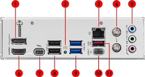
That distinction matters when retaining an external SSD enclosure or dock. Record its actual protocol and cable requirement before choosing a port. A USB4 device does not gain a documented 40Gbps path here merely because the board's connector says Thunderbolt 4. The separate 5Gbps Type-C connection is a different data path again.
For video, MSI lists DisplayPort 2.1 over the Thunderbolt port, with maximum 4K at 120Hz or 8K at 60Hz, only with a processor featuring integrated graphics, and subject to the installed CPU. Match the actual display, dock and cable as well; these listed modes are not a guarantee for every connected combination.
MSI also lists JTBT5_1, a connector for its Thunderbolt 5 expansion card. That header does not make this board's existing rear port Thunderbolt 5. An expansion card would need its own compatibility, slot and connection plan; it is not in the manual's package inventory.
6. Compare TUF’s Rear Ports with the Actual Peripherals
TUF's rear Type-C port is USB 20Gbps with DisplayPort Alt Mode, with the specification listing up to 5V/3A power delivery. Its DisplayPort video specification is up to 4K at 60Hz, with CPU-dependent graphics conditions. This is useful connectivity to assign explicitly, rather than treating every Type-C device as needing Thunderbolt.
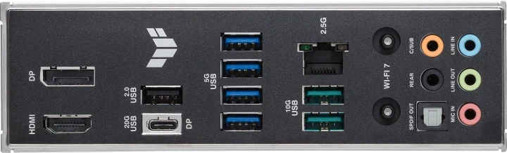
There is also an important setup instruction: during operating-system installation, ASUS says to connect the monitor to rear HDMI or a discrete graphics card. Plan that initial display connection even if a Type-C display connection is intended afterward. The internal Thunderbolt/USB4 header is separate from the rear 20Gbps port; it does not establish an onboard Thunderbolt or USB4 port.
| Rear Type-A inventory | TUF | MSI Gaming Plus |
|---|---|---|
| 10Gbps | Two | One |
| 5Gbps | Four | Two |
| USB 2.0 | One | Two |
TUF therefore has seven rear Type-A ports, while MSI has five, alongside their different Type-C arrangements. Assign retained external drives to the appropriate faster ports and account for keyboards, controllers and other peripherals separately. Count the required connections before deciding that onboard Thunderbolt outweighs the Type-A difference.
Other retained connections can settle the choice. TUF lists 2.5Gb Ethernet, five audio jacks and optical S/PDIF; MSI lists 5Gb Ethernet and three audio jacks. Match the actual network and audio connections, not just the faster network-port rating. Both boards' Wi-Fi features also carry operating-system and regional conditions.
7. Count Front-panel Leads and Internal USB Users
Both boards support one front Type-C connection up to 10Gbps. The remaining internal USB capacity differs: TUF lists one 5Gbps header supporting two ports and one USB 2.0 header supporting two ports. MSI lists two 5Gbps headers supporting four ports and two USB 2.0 headers supporting four ports.
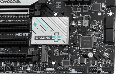
MSI identifies the front Type-C connector as JUSBC1, the 5Gbps headers as JUSB3/JUSB4, and the USB 2.0 headers as JUSB1/JUSB2. Its actual lower-board detail shows the two 5Gbps headers beside the SATA and lower-card region. Its component map places JUSBC1 higher on the right edge.
For example, retaining two separate front Type-A header leads requires two suitable native headers if both leads are to connect that way. MSI lists two; TUF lists one. Include internal devices using USB 2.0 in the same inventory, so the case's front ports do not consume connections already assigned to a retained controller.
These are supported port counts, not promises of independent full bandwidth for every port at once. MSI's manual identifies hubs in its front USB paths. A rear Type-C socket also cannot stand in for the internal connector required by a case's front Type-C lead.
8. Finish the SATA, Power and Package Inventory
Four SATA ports on either board require a separate check of four drive mounting positions, suitable SATA data leads and PSU drive-power connections in the intended case. TUF lists two SATA data cables in its accessories; MSI lists one. Neither package supplies four simply because four ports are present.
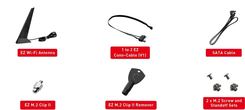
TUF also lists its Wi-Fi Q-Antenna, two M.2 rubber packages and an M.2 screw package. MSI's package image and manual identify an EZ Wi-Fi Antenna, a 1-to-2 EZ Conn-Cable V1, one EZ M.2 Clip II, its remover, and two M.2 screw-and-standoff sets. Confirm the actual supplied items, particularly the mounting pieces required by the retained drives.
Power connections differ. ASUS lists a 24-pin main connector and two 8-pin +12V connectors. MSI's manual specifies a 24-pin main connector, an 8-pin CPU connector, a 4-pin CPU connector and an additional 8-pin PCIe-power connector. Its web page's count of two CPU-power connectors should not be read as two 8-pin connectors. Use the selected board's instructions and appropriate PSU cables alongside the GPU's own requirements.
Check cooling leads too: TUF lists CPU Fan, CPU OPT, AIO Pump and three chassis-fan headers; MSI lists CPU Fan, a pump/system-fan header and three system-fan headers. Retain the intended functions and actual connectors rather than assuming identical header arrangements.
9. Choose from a Complete Retained Configuration
Choose TUF when the plan is a GPU plus one suitable chipset-connected x4 card, three 2280 PCIe SSDs with x4 connections, and peripherals fitting its rear 20Gbps Type-C and seven Type-A ports. Confirm the two card positions remain physically accessible, the exact RAM and BIOS work, and the case's leads fit its smaller internal USB inventory.
Choose MSI Gaming Plus when the extra x1 positions or its documented Thunderbolt-device connection solve a real retention need. A short 2242 SSD can occupy M2_1, with the other drives assigned to M2_2 and rear M2_3. Accept the third drive's x2 link and underside-access requirement, and establish that the GPU does not obstruct the additional cards you intend to keep.
For either choice, place the actual CPU, memory kit, cards, three SSDs, four SATA-drive provisions, PSU leads and external devices in that one plan. The better board is the one that preserves the complete arrangement after its physical and protocol limits are applied.