For a Ryzen 7000 or 9000 rebuild retaining a GPU, a second x4 card and three onboard NVMe SSDs, both MSI MAG B850M MORTAR WIFI and ASRock B850M Riptide WiFi have useful documented layouts. The important difference is where their resources go: Mortar supplies two CPU-connected Gen 5 M.2 positions and a chipset-connected Gen 4 x4 card slot. Riptide supplies one CPU-connected Gen 5 M.2 position and a CPU-connected Gen 4 x4 second card slot. Its other two SSD positions connect through the chipset.
Choose from that complete assignment rather than counting three M.2 sockets and stopping there. Mortar's third SSD goes on the back of the board at Gen 4 x2. Riptide's chipset SSD positions offer Gen 4 x2 and x4, while its front Type-C connection is slower than Mortar's. Four memory sockets and four SATA ports on each board complete the retention question.
1. Establish the CPU and Four-module Memory Plan
The main comparison here concerns Ryzen 7000/9000 and ordinary non-ECC, unbuffered DDR5. Find the exact retained CPU in the chosen board's support list and confirm its required BIOS before dismantling the current PC. Both manufacturers support AM5 processor families, but that family-level statement does not make every CPU configuration electrically identical.
Both boards have four DDR5 sockets and a published maximum of 256GB. That makes them candidates for a retained four-module kit in a way that a two-socket Mini-ITX board is not. It does not validate the exact kit, all four modules at their old settings, or an advertised maximum overclocked rate. Check the actual CPU, memory part numbers and four-module configuration against the selected board's memory support information.
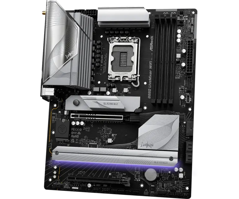
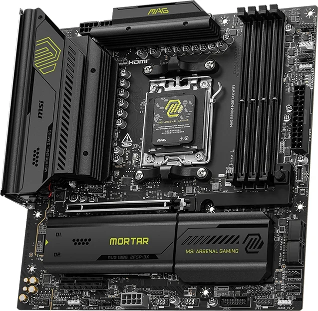
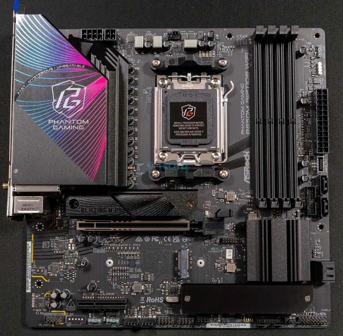
For example, retaining four suitable 16GB desktop modules preserves a possible 64GB configuration without buying a two-module replacement solely because of socket count. Physical fit around the CPU cooler still matters. The Riptide whole-board photograph shows its four sockets along the right edge; Mortar's title image likewise shows four desktop memory positions.
Keep Ryzen 8000 separate from the primary allocation below. Both boards list lower GPU and main-SSD link modes for that family, with further differences between CPU groups. In particular, do not assume Riptide's second CPU card connector retains the same availability without checking the exact CPU's bandwidth table.
2. Decide Whether the Second x4 Card Must Connect to the CPU
With Ryzen 7000/9000, both main GPU positions are listed at up to PCIe 5.0 x16. Their second connectors have the same advertised lane width and generation but different upstream connections. The manufacturer block diagrams confirm the distinction.
| Board | Second card connector | Documented connection |
|---|---|---|
| Mortar | PCI_E2 | Chipset, up to PCIe 4.0 x4 |
| Riptide | PCIE2 | CPU, up to PCIe 4.0 x4 |
If the retained card's documentation specifically requires a CPU-connected slot, Riptide is the candidate of these two. If it accepts a chipset-connected Gen 4 x4 path, Mortar remains a candidate and gives the CPU storage lanes to its second Gen 5 SSD position instead. Confirm the card's actual generation, electrical-width and compatibility requirements; its x4 edge connector alone does not answer every part of that question.
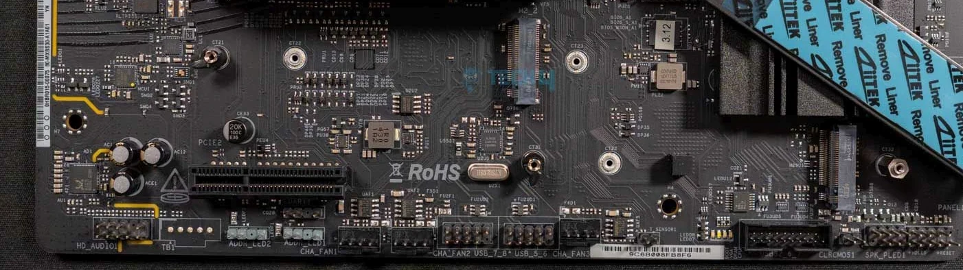
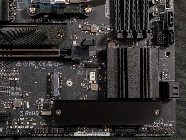
The Riptide close-up shows the short lower PCIE2 connector near the board's bottom edge, with storage heatsinks lifted in the photograph. Check the actual card's connector and bracket against that position. A thick GPU cooler, the case floor or a PSU shroud can prevent access even when the lane assignment works.
A CPU connection is a routing distinction, not a universal performance ranking. Mortar's chipset-connected card also shares the chipset's upstream resources with other chipset devices. Neither a separate connector nor a nominal x4 link establishes unrestricted simultaneous capture, storage and network throughput.
3. Assign All Three SSDs by Slot Name, Link and Length
The three-position inventories differ substantially. The table applies to the Ryzen 7000/9000 configuration and gives each connector's specified maximum link. All are the boards' PCIe storage positions; the separate Key E wireless socket is not another NVMe-drive position.
| M.2 position | Mortar | Riptide |
|---|---|---|
| M2_1 | CPU Gen 5 x4; 2260/2280 | CPU Gen 5 x4; 2280 |
| M2_2 | CPU Gen 5 x4; 2260/2280 | Chipset Gen 4 x2; 2260/2280 |
| M2_3 | Chipset Gen 4 x2; 2280; rear of board | Chipset Gen 4 x4; 2260/2280 |
For Mortar, put the two drives needing Gen 5 connections in M2_1 and M2_2, then evaluate the third 2280 NVMe drive for M2_3. For Riptide, the Gen 5 position is M2_1; choose between M2_3's Gen 4 x4 and M2_2's Gen 4 x2 according to the retained drives and their roles. The slot numbers do not rank the chipset connections in ascending speed.
For example, three retained 2280 NVMe drives fit the listed length options on either board, subject to the exact drives and cooling arrangements. A retained 2260 drive has more limited choices: it can use either of Mortar's front CPU positions, but not its rear M2_3. On Riptide it belongs in M2_2 or M2_3, not the 2280-only M2_1 position.
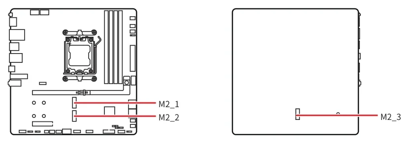
Mortar's original front/back drawing is especially useful before case assembly. It places M2_1 and M2_2 on the front and M2_3 on the rear. Do not plan all three SSDs around access from above the GPU.
These layouts provide an on-paper route for the GPU, second x4 card and three onboard PCIe SSDs without treating an additional storage card as free expansion. Keep the x2 position in the plan rather than describing either board as three identical x4 SSD connections. An M.2 SATA drive also needs a different connection plan from these documented PCIe positions.
4. Check the Rear Drive and Heatsinks Against the Actual Case
Both boards are approximately 244mm square mATX designs. A case accepting that footprint still needs room for the retained GPU, lower card, cooler, cables and storage. For Mortar, add the underside SSD to that physical check. Measure the drive and any heatsink against the tray and standoff space at the actual M2_3 location. A CPU-backplate cutout helps only if the relevant area is accessible.
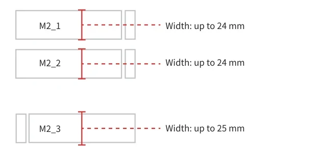
MSI's original clearance drawing gives 24mm maximum heatsink width for M2_1 and M2_2, and 25mm for M2_3. Those are width limits, not a clearance guarantee for every heatsink height. The manual also says to consider the installed PCIe card's height when checking M.2 space.
For a drive with its own heatsink, follow MSI's instruction to remove the M.2 plate or rubber cube as applicable and not reinstall the motherboard-supplied heatsink on top. Complete the underside-drive fit and access check before fastening the board into the case if the tray will obstruct later access.
Do not transfer Mortar's numerical limits to Riptide. Use the selected drive, fitted heatsink and surrounding hardware for that board's fit check. Riptide's visible uncovered M2_2 area in the photographs identifies a position; an x2 link rating does not establish that a particular SSD needs no cooling.
5. Preserve the Case’s Front Ports at Their Actual Speeds
The front Type-C lead is a meaningful difference if you want to retain the case and its wiring. Mortar provides one front Type-C connection up to 10Gbps. Riptide provides one up to 5Gbps, through its USB32_TC2 header. A Type-C-shaped socket on the case does not change the motherboard's supported data rate.
| Front USB provision | Mortar | Riptide |
|---|---|---|
| Type-C | One 10Gbps connection | One 5Gbps connection |
| 5Gbps Type-A capacity | One header for two ports | Two headers for four ports |
| USB 2.0 capacity | Two headers for four ports | Two headers for four ports |
The Riptide detail photograph shows the front-header region beside the memory, chipset heatsink and SATA area. Its manual names the two front Type-A headers USB32_4_5 and USB32_6_7, separate from USB32_TC2. Count the retained case's actual cables as well as its visible sockets.
For example, a case with two separate front USB Type-A header leads can use Riptide's two listed 5Gbps headers, subject to matching cables. Mortar lists one such header, so both leads cannot simply be assigned to separate native 5Gbps headers there. Likewise, a front Type-C requirement above 10Gbps is not established by either board's front connection.
Keep the rear ports out of this header count. A fast Type-C port on the rear I/O panel does not provide the internal connector needed by a front-panel cable.
6. Compare Rear USB and Network Needs Alongside the Retained Peripherals
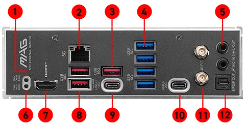
Mortar has two rear Type-C ports, one 10Gbps and one 20Gbps. Its seven rear Type-A ports comprise three 10Gbps and four 5Gbps connections. The manufacturer rear I/O image helps distinguish the two Type-C positions from the adjacent Type-A groups.
Riptide has one rear 10Gbps Type-C port. Its seven rear Type-A ports comprise one 10Gbps, two 5Gbps and four USB 2.0 connections. Equal Type-A counts therefore do not mean equal speed inventories. Assign the actual external SSDs, peripherals and cables before deciding that all seven positions are interchangeable.
Neither documented Type-C inventory here establishes USB4 or Thunderbolt. Match data, display and charging requirements separately rather than inferring them from the connector shape.
The wired network difference is 5GbE on Mortar versus 2.5GbE on Riptide. Choose from the actual network path, switch and transfer needs; the motherboard port rating is not an internet-speed guarantee. Both boards advertise Wi-Fi 7 with operating-system and regional conditions, so check the selected wireless configuration if that is part of the migration.
7. Count SATA Cables, Drive Mounts and Power Connections
Each board provides four SATA 6Gb/s connectors. Retaining four SATA drives also requires four usable drive mounting positions, four suitable data leads and enough PSU connections in the new case. A smaller motherboard does not create those drive bays.
Mortar's manual lists one SATA cable in the package. It also lists an EZ Front Panel Cable, a 1-to-2 EZ Conn-Cable V1, two EZ M.2 Clip II pieces, a clip remover and an M.2 screw set. Retain the appropriate existing leads and check the mounting pieces rather than assuming a four-port board supplies four cables.
ASRock's product page lists two SATA data cables, two antennas, M.2 screws, a standoff and a thermistor cable. Its manual marks the accessories optional, so confirm the actual unit's package. Even two included SATA leads would leave two more to account for in a four-drive plan.
The PSU cable inventory differs too. Mortar lists a 24-pin main connector, two 8-pin CPU-power connectors and an additional 8-pin PCIe-power connector. Riptide lists a 24-pin main connector, an 8-pin CPU-power connector and a 4-pin CPU-power connector. Check the chosen board's connection instructions and your PSU's appropriate cables, alongside the GPU's own requirements. The connector list is not permission to substitute one cable type for another.
8. Choose from the Complete Retained Configuration
Choose Mortar when the retained x4 card accepts its chipset connection and two onboard Gen 5 SSD links matter. A complete example is GPU in PCI_E1, retained card in PCI_E2, two suitable SSDs in M2_1/M2_2 and the third 2280 SSD at rear M2_3. Confirm the x2 third-drive path, underside clearance, four-module memory configuration and front-header count before ordering.
Choose Riptide when a CPU-connected second x4 slot is the deciding requirement and one Gen 5 SSD position is sufficient. A complete example is GPU in PCIE1, retained card in PCIE2, one SSD in M2_1 and the other two in M2_3/M2_2, with their Gen 4 x4/x2 links recorded. Check card access and each drive's length, then match the case's front Type-C and Type-A leads to their separate headers.
For either board, finish the list with the actual CPU and BIOS, four memory modules, all drive mounts and cables, PSU connections and retained peripherals. The useful choice is the board that preserves that full arrangement, including its slower link and physical constraints, rather than the one with the most impressive isolated maximum.