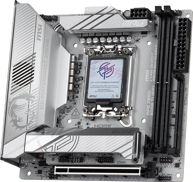
The MPG Z890I EDGE TI WIFI's four-drive specification depends on more than the motherboard alone. Its fourth M.2 position is on the dedicated 5-in-1 XPANDER, which also supplies two SATA connections and the main high-speed front USB connections. The second M.2 position uses a separate removable M.2 adapter assembly.
Before buying an incomplete board or transferring it into a smaller case, inventory those two different cards, the dedicated USB cable and the SSD fixing hardware. A missing accessory can change both the storage plan and which case-front sockets work. Counting the SSDs in your old machine is only the beginning.
The XPANDER Belongs in Its Dedicated Slot
The real installed-card view shows XPANDER beside the board edge. MSI assigns it exclusively to FP_CARD1. It is separate from the board's single CPU-connected PCIe Gen5 x16 expansion slot.
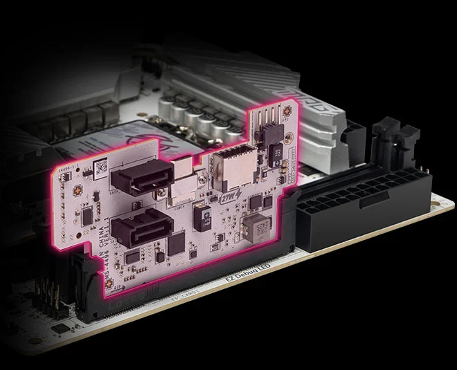
Without XPANDER, you lose its M2_4 position, both SATA ports, the front 20Gbps Type-C connection, the two front 5Gbps Type-A connections and JFP2. JFP2 serves a buzzer or speaker; the power/reset switches and case LEDs use the motherboard's JFP1 instead.
This is why a used-board listing needs more than a top-view photograph. Ask for a clear view of the actual XPANDER and the accessories being supplied. A seller saying that the board has four M.2 slots does not establish that the parts required for all four are present.
Do not budget an ordinary PCIe storage adapter as a direct replacement for this card. Your intended GPU already has a place in the expansion-slot plan, while FP_CARD1 requires its matching accessory. Resolve the missing original hardware before assuming that a similarly shaped card restores the lost functions.
Map Four Actual SSDs to Four Different Positions
All four M.2 positions support 2280 modules. Their routes and protocols differ as follows. The native map distinguishes the upper assembly, its removable adapter, the motherboard underside and the XPANDER underside.
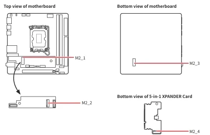
| Position | Route and protocol | Physical location |
|---|---|---|
| M2_1 | CPU PCIe Gen5 x4 | Upper M.2 assembly |
| M2_2 | CPU PCIe Gen4 x4 | Removable M.2 adapter |
| M2_3 | Chipset PCIe Gen4 x4 or SATA | Motherboard underside |
| M2_4 | Chipset PCIe Gen4 x4 | XPANDER underside |
M2_4 requires a single-sided SSD without its own heatsink. M2_3 is the SATA-capable M.2 position; XPANDER's two SATA cable connections are separate from that socket.
For example, suppose you are keeping three 2280 PCIe SSDs and one 2280 SATA M.2 drive. Reserve M2_3 for the SATA module. One of the PCIe drives must meet M2_4's single-sided, heatsink-less restriction, while the other two go into the upper assembly's positions. That is a usable allocation only after confirming the actual modules and both required cards.
A different inventory can fail the same paper count. Four drives that include a shorter-only module, or no suitable bare single-sided drive for M2_4, cannot simply be entered into the four rows as though their physical formats were interchangeable. Keep the drive model and physical construction beside each proposed position.
Keep the M.2 Adapter and Its Screws Separate from XPANDER
MSI's M2_2 procedure removes the upper heatsink, loosens the M.2 adapter's screws and lifts out the adapter. The SSD installs on its other face. The adapter then returns to M2_SWITCH1 and is secured before the heatsink is refitted.
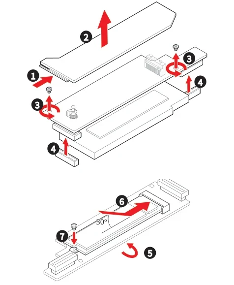
The native drawing makes this arrangement more useful to inspect than a generic “four SSDs supported” claim. Keep the removable adapter itself, its securing screws, the SSD screw and the heatsink assembly in your inventory. Finding XPANDER in the box does not establish that this separate assembly is complete.
For M2_3 and M2_4, the manual specifies the supplied M.2 8.5H screw. Its package list includes M.2 screw packs and the dedicated XPANDER USB 5Gbps cable.
Identify the proper fixing hardware rather than trying a loose screw because it appears to start in the hole. If parts are missing, describe the exact position and original assembly when seeking the correct replacement. “An M.2 screw” is too vague to settle which retained hardware is suitable.
Also plan access to the underside SSD before fastening the board into the new case. Check the actual tray opening and any obstruction behind it. A rear socket in the manual establishes its location, not that every compact case permits servicing it with the motherboard installed.
Inspect Both XPANDER Faces and the Dedicated USB Cable
The numbered manufacturer view shows both faces of the real card: 1 is JFP2, 2 is the front Type-C connector, 3 marks the two SATA connectors, 4 is the dedicated USB 5Gbps connection, and 5 is the M.2 socket.
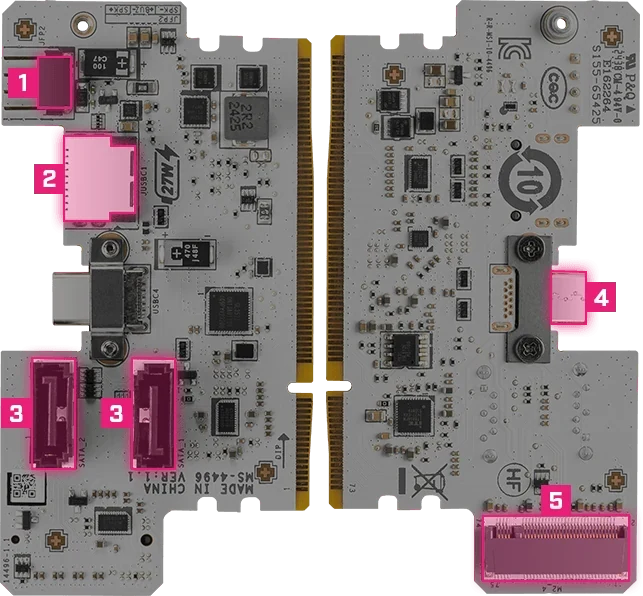
Use those visible features when checking a parts photograph. Inspect the actual connectors, the SSD side and the card-edge contacts, rather than accepting a distant image of an unspecified accessory. A photograph can identify what is being offered; it cannot establish the condition of every electrical connection.
The USB 5Gbps cable is a separate item from XPANDER. MSI's wiring drawing routes the case's USB 5Gbps lead through that dedicated cable to the card's USBC4 connector. A cable that merely resembles a USB-C cable is not evidence of the correct connection.
If you are also retaining cable-connected SATA drives, reserve their case mounts and PSU power connections as well as the XPANDER data ports.
Check the card and cable independently. If one is absent, leave the corresponding front-port connection unresolved in your plan. Buying a complete board package may make more sense than assembling uncertain accessories individually, but compare the actual contents and total cost rather than assuming either route is cheaper.
Trace Each Case-front Cable to Its Real Destination
The two native cable paths are different: the case's front Type-C lead connects to JUSBC1; the front 5Gbps lead uses the dedicated XPANDER cable and USBC4. The specification lists up to 27W PD for JUSBC1.
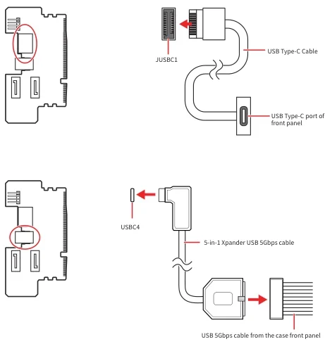
| Case connection | Required destination | What to check |
|---|---|---|
| Front Type-C | XPANDER JUSBC1 | Case lead and supported front-port specification |
| Front USB 5Gbps Type-A pair | XPANDER USBC4, through dedicated cable | Correct cable is included |
| Front USB 2.0 | Motherboard JUSB1 | Actual case USB 2.0 lead |
| Power/reset and indicator LEDs | Motherboard JFP1 | Correct labelled pins and LED polarity |
| Buzzer or speaker | XPANDER JFP2 | Required only if you use that device |
| Front audio | Motherboard audio header | Case front-audio lead |
The motherboard's component and connector pages distinguish these onboard connections from XPANDER's connectors. A missing card therefore does not mean every case-front function disappears.
For the retained case, lay out its actual cables and mark which rows you need. A Type-C socket on the exterior does not prove that its cable and port can deliver the motherboard's maximum data rate or charging capability. Keep those requirements separate from the simpler question of whether the required board-side connector exists.
Finish the Smaller-build Inventory Before Committing
This is a 170 × 170mm Mini-ITX board for LGA1851 Intel Core Ultra Series 2 processors, with two DDR5 DIMM slots, one main expansion slot and three conventional fan headers: CPU, pump/system and system.
If your larger machine uses four memory modules or a second expansion card, account for those retained parts explicitly. Four storage positions do not preserve all the expansion capacity of a larger board. Likewise, list the fans and pump connections your smaller case actually needs, rather than assuming every existing lead has a spare header.
Before purchase, you should have four named SSD assignments, both necessary card assemblies, the correct fixing hardware and a destination for each required front cable. Then check the complete case, cooler and GPU arrangement. An incomplete package is a conditional candidate until its missing parts are resolved; the advertised drive count cannot resolve them for you.